

Electromagnetostrictive actuator
a technology of electromagnetic restriction and actuator, applied in the direction of magnets, generators/motors, magnetic bodies, etc., can solve the problems of difficult to adopt the above-mentioned construction, complicated entire apparatus including control systems
- Summary
- Abstract
- Description
- Claims
- Application Information
AI Technical Summary
Benefits of technology
Problems solved by technology
Method used
Image

Examples
first embodiment
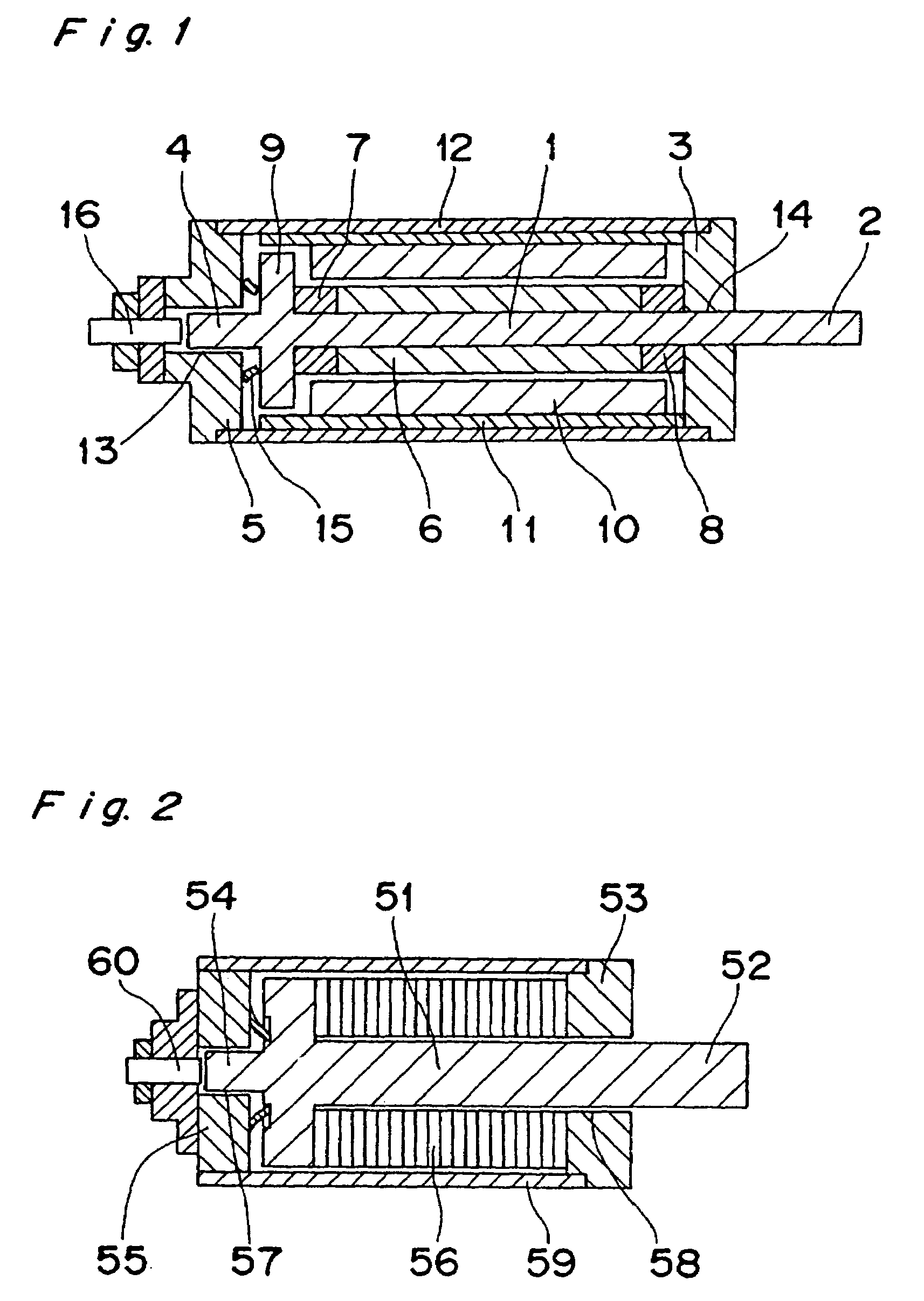
[0044]the present invention will be described below with reference to FIG. 1.
[0045]FIG. 1 shows a direct-acting type actuator that employs a Giant-magnetostrictive element, in which a displacement sensor for detecting the position in the axial direction of an output shaft is arranged in an axial core portion located opposite to the output side.
[0046]The apparatus includes a piston (one example of an output shaft) 1 driven by the actuator, a front-side (output-side) end portion 2 of the piston 1, a front-side sleeve 3 that supports the front side of the piston 1, a rear-side end portion 4 of the piston 1, and a rear-side sleeve 5 that supports the piston 1 on the rear side. The apparatus further includes a Giant-magnetostrictive rod 6 that is made of a Giant-magnetostrictive material and has a cylindrical shape. This Giant-magnetostrictive rod 6 is fixed between a rear-side yoke 9 and the front-side sleeve 3 that concurrently serves as a yoke member with interposition of first and se...
second embodiment
[0055]the present invention will be described below.
[0056]FIG. 2 shows an application of the present invention employing an actuator of a laminate type piezoelectric element, which is an electromagnetostrictive element. This embodiment of the invention includes a piston (one example of an output shaft) 51 driven by the actuator, a front-side (output-side) end portion 52 of the piston 51, a front-side sleeve 53 for supporting the piston 51 on the front side, a rear-side end portion 54 of the piston 51, and a rear-side sleeve 55 for supporting the piston 51 on the rear side. A laminate-type piezoelectric element 56, which is formed into a hollow shape, is mounted between the rear side of the piston 51 and the front-side sleeve 53 that serves as a fixed side. The rear side 54 of the piston 51 is movably supported in the axial direction by a bearing portion 57. The front side of the piston 51 is also supported by a bearing portion 58. A housing 59 houses therein the members 51 through 5...
third embodiment
[0058]the present invention will be described below.
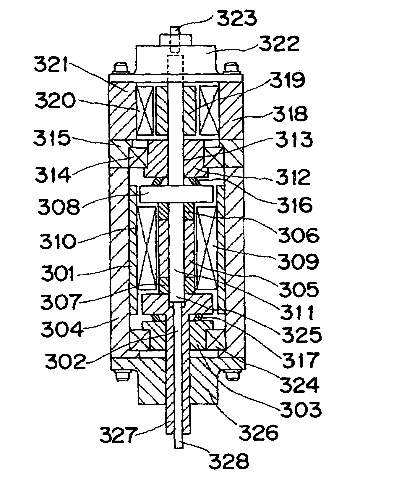
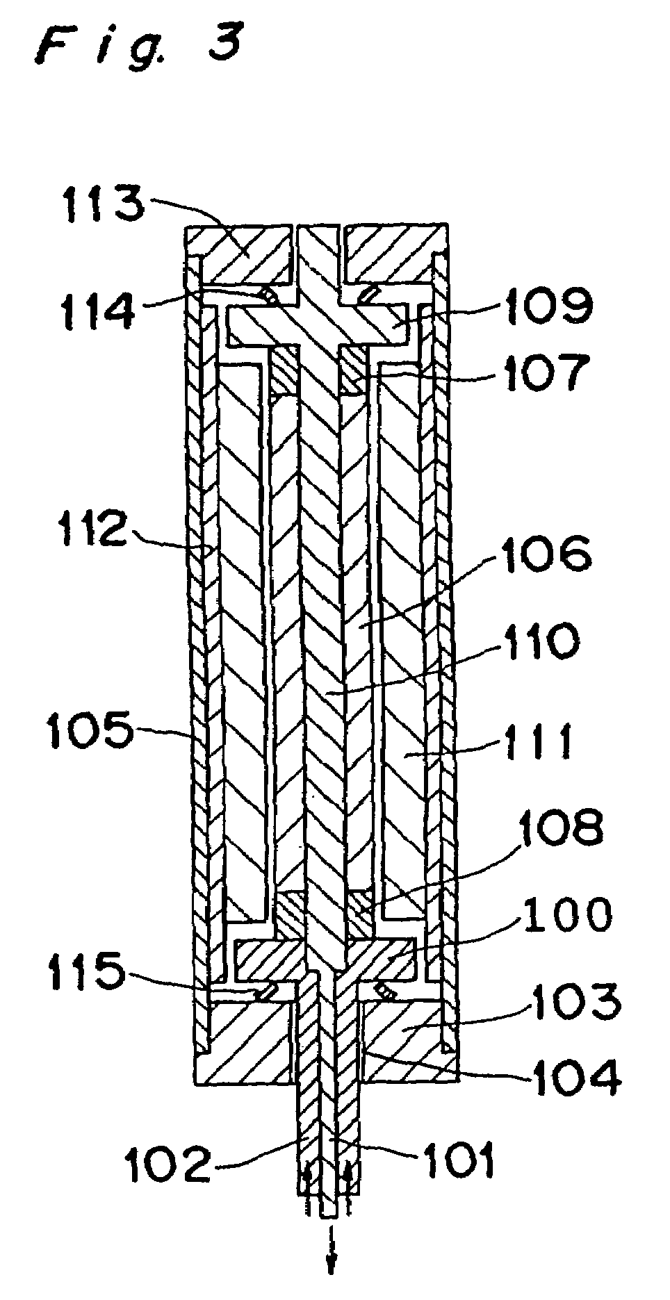
[0059]According to this third embodiment, an actuator having two output shafts with a phase difference of 180 degrees is constructed by utilizing an output displacement at both end portions of a Giant-magnetostrictive rod, paying attention to the phenomenon that the entire Giant-magnetostrictive element extends or contracts in the direction of the magnetic field.
[0060]This embodiment of the invention includes a piston (one example of a first output shaft) 100, a front-side small-diameter section 101 of this piston 100, a movable sleeve (one example of second output shaft) 102 for supporting the small-diameter section 101 of the piston 100, a front-side sleeve 103 for supporting this movable sleeve 102 relatively movably in the axial direction, and a bearing portion 104. The invention also includes a housing 105 and a cylindrical Giant-magnetostrictive rod 106 made of a Giant-magnetostrictive material. This Giant-magnetostrictive ro...
PUM
| Property | Measurement | Unit |
|---|---|---|
| Giant-magnetostrictive | aaaaa | aaaaa |
| displacement | aaaaa | aaaaa |
| giant magnetostriction | aaaaa | aaaaa |
Abstract
Description
Claims
Application Information