
Traffic management system

a technology of traffic management and system, applied in the field of traffic management system, can solve the problems of time-consuming and labor-intensive adjustment of devices after installation, affecting the use of vehicles, and imposing financial burden on users

Inactive Publication Date: 2008-01-29
FUJITSU LTD
View PDF13 Cites 28 Cited by
  • Summary
  • Abstract
  • Description
  • Claims
  • Application Information

AI Technical Summary

Benefits of technology

[0011]It is therefore an object of the present invention to provide a traffic management system for performing high-quality management control over various vehicle traffic situations.

Problems solved by technology

Therefore, the entire system is large in scale, a long period of time is required for installing the devices in place, and adjusting the devices after being installed is time-consuming.
However, inasmuch as the vehicle information including the vehicle position and the time information is transmitted from the vehicle to the fixed station, the vehicle has to be equipped with a device of high functionality, such as a car navigation unit for measuring the vehicle position based on GPS, which poses a financial burden on the user of the vehicle.
Another problem is that the system does not perform sophisticated traffic management control for predicting the position of a traffic accident and a faulty vehicle and notifying nearby vehicles of the accident information.

Method used


Image

  • Traffic management system
  • Traffic management system
  • Traffic management system

Examples


Embodiment Construction

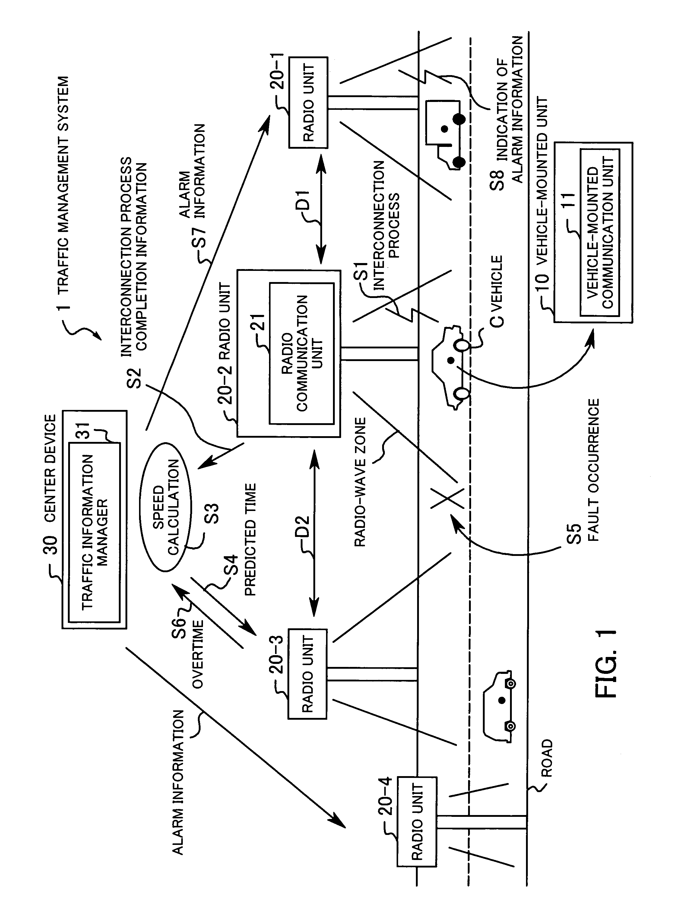
[0041]FIG. 1 shows the principles of a traffic management system 1 according to the present invention. As shown in FIG. 1, the traffic management system 1 comprises a vehicle-mounted unit 10, a plurality of radio units 20-1 through 20-4 (collectively referred to as “radio unit 20”), and a center device 30. The traffic management system 1 serves to manage the traffic situation of a vehicle C.

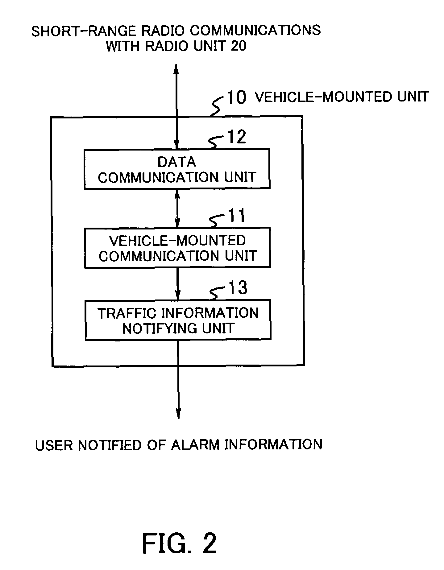
[0042]The vehicle-mounted unit 10, which is mounted on the vehicle C, has a vehicle-mounted communication unit 11 for communicating with the center device 30 via the radio unit 20. The vehicle-mounted communication unit 11 performs an interconnection process (i.e., a user authentication process) when entering a radio-wave zone (communication area) provided by the radio unit 20, using an individual vehicle ID assigned to the vehicle C. Alternatively, the vehicle-mounted communication unit 11 may send the vehicle ID via the radio unit 20 to the center device 30 for the center device 30 to perform t...


PUM


Abstract

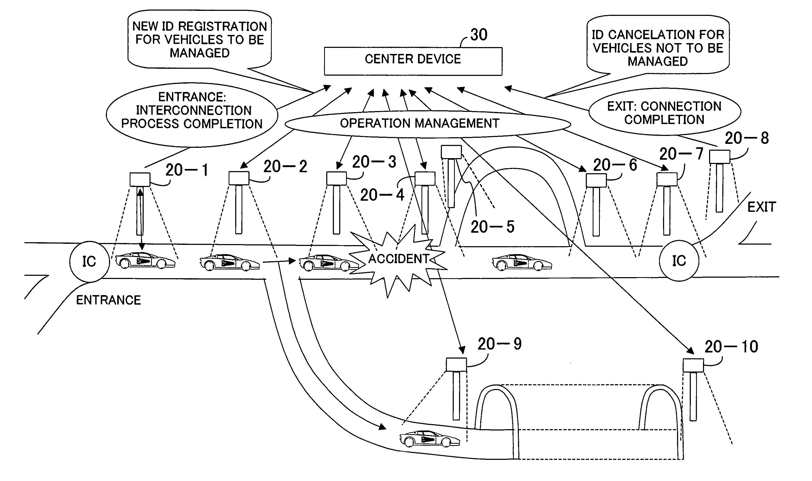
A traffic management system manages, distributes, and controls various traveling states of vehicles at a high quality level. A vehicle-mounted unit performs an interconnection process for user authentication when entering a predetermined radio-wave zone. A radio unit disposed on a road sends interconnection process completion information to a center device when the interconnection process for connection to the vehicle is completed. If the vehicle does not connect to the radio unit after elapsed of a predicted time at which the vehicle is expected to travel across the radio unit, then the radio unit sends an overtime to the center device. The interconnection process completion information is received, the center device calculates a predicted time at which the vehicle is expected to pass across a radio unit, and sends the predicted time to the radio unit. When the overtime is received, the center device determines whether a fault has occurred or not. When it is judged that the fault has occurred, the center device sends alarm information to vehicles traveling near a site where the fault has occurred on the vehicle.

Description

CROSS-REFERENCE TO RELATED APPLICATIONS[0001]This application is based upon and claims the benefits of priority from the prior Japanese Application No. 2004-082221, filed on Mar. 22, 2004, the entire contents of which are incorporated herein by reference.BACKGROUND OF THE INVENTION[0002](1) Field of the Invention[0003]The present invention relates to a traffic management system, and more particularly to a traffic management system for managing vehicle traffic.[0004](2) Description of the Related Art[0005]In recent years, attention has been attracted to 5.8 GHz short-range radio communications (DSRC: Dedicated Short-Range Communications) typified by an ETC (Electronic Toll Collection) system which automatically collects tolls from moving vehicles without the need for the vehicles to stop at expressway toll booths. The development of a system of sophisticated networks of roads and vehicles using such short-range radio communications is now in progress.[0006]FIG. 29 of the accompanying...

Claims


Application Information

Patent Timeline
Patent Type & Authority Patents(United States)
IPC IPC(8): G08G1/00G06F19/00G08G1/09G08G1/01G08G1/017G08G1/123G08G1/16H04B7/26H04W4/02H04W4/04
CPCG08G1/017G08G1/164G08G1/205
Inventor YAMASHITA, KIYOHIDENAGANO, YUJINOMURA, YUJIOGURA, HIROSHINAGAI, KAZUYOSHIOHASHI, TAKATOOKAMURA, KANNA
Owner FUJITSU LTD
Learn More