
Equipment installation support on foundation

a technology for equipment and support, applied in the direction of machine supports, auxillary members of forms/shuttering/falseworks, furniture parts, etc., can solve the problems of cumbersome, difficult assembly, installation and adjustmen

Inactive Publication Date: 2008-02-12
MCDONNELL THOMAS
View PDF23 Cites 30 Cited by
  • Summary
  • Abstract
  • Description
  • Claims
  • Application Information

AI Technical Summary

Problems solved by technology

However, when support of the equipment on the foundation involves establishing a somewhat non-parallel relationship between the attachment surfaces of the equipment and the foundation to which the tapered wedges are bolted, assembly, installation and adjustment becomes difficult and cumbersome.

Method used


Image

  • Equipment installation support on foundation
  • Equipment installation support on foundation
  • Equipment installation support on foundation

Examples


Embodiment Construction

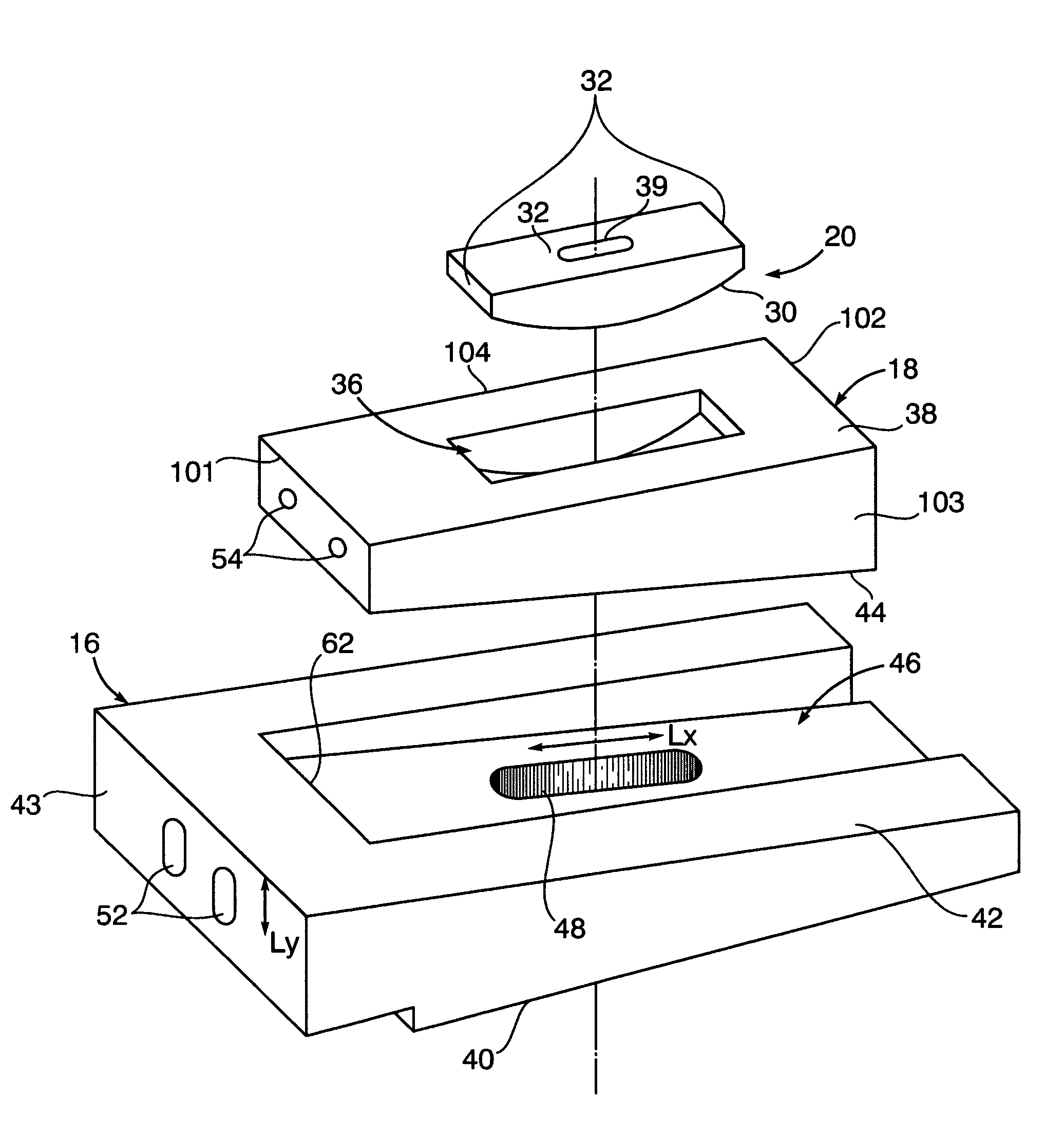
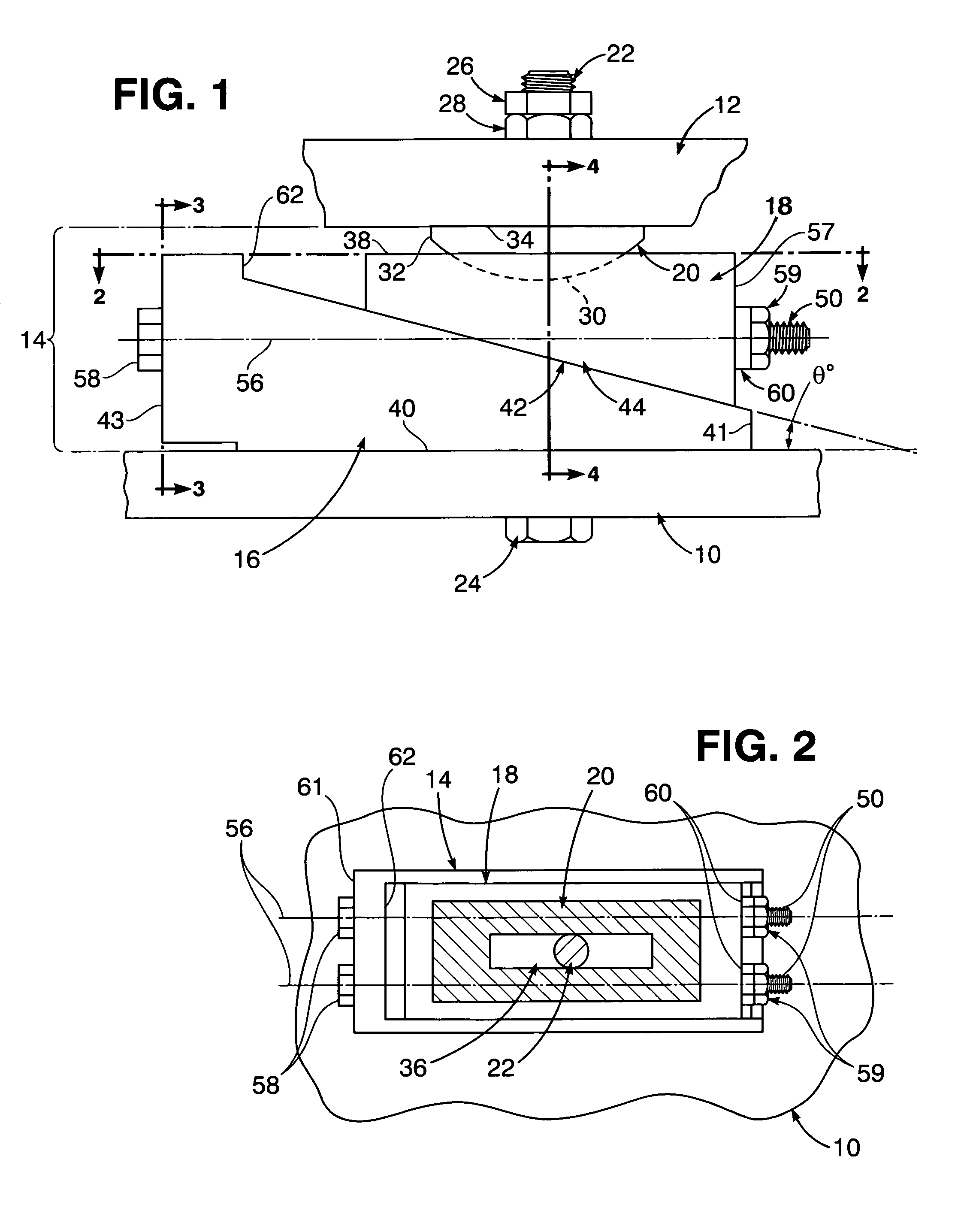
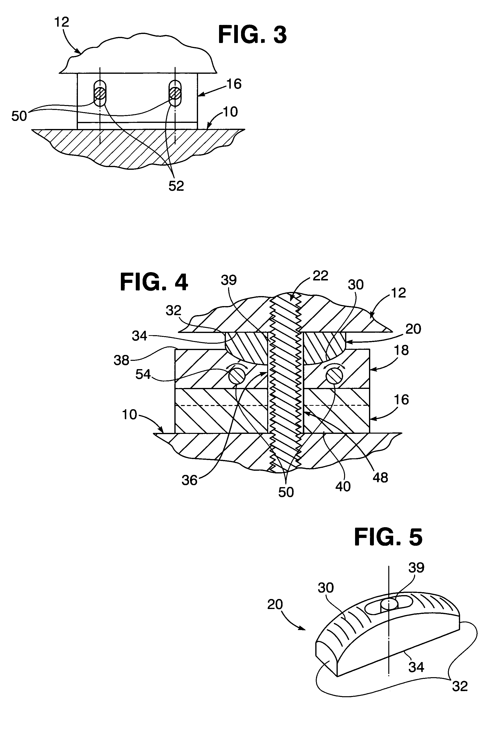
[0010]Referring now to the drawing in detail, FIG. 1 illustrates a portion of a foundation 10 loaded by equipment 12 installed thereon in an adjusted position by a support assembly 14 disposed between the equipment 12 and the foundation 10. The support assembly 14 includes a lower tapered wedge 16 positioned on the foundation 10, an upper tapered wedge 18 that is adjustably positioned on the lower tapered wedge 16 and a bearing washer 20 inserted into the top of the upper wedge 18 and on which the equipment 12 is positioned. As shown in FIG. 6, the upper tapered wedge 18 includes a first end 101, a second end 102, a first side 103, and a second side 104, the first and second sides substantially perpendicular to the first and second ends. The portion of the equipment 12 adjustably positioned by the support assembly 14 on the foundation 10 is fastened thereto by a vertical threaded bolt 22 having a head 24 at its lower end in abutment with the foundation 10 and a lock nut 26 is thread...


PUM


Abstract

A bearing washer is inserted into a horizontally elongated recess formed within the top flat surface of an upper tapered wedge of a support assembly through which equipment is adjustably positioned on a foundation. The upper wedge is vertically and horizontally adjusted in slidingly positioned contact with a lower tapered wedge along inclined surfaces within a recess formed therein before attachment of the tapered wedges to each other by horizontal fastener bolts extending through the upper wedge and the lower wedge. In such adjusted position of the wedges, a convex surface on the inserted bearing washer is in contact with a concave surface within a recess formed in the top surface of the upper wedge to support the equipment in close spaced relationship thereabove. Slidable adjustment of the wedges is limited by a recess shoulder in the lower tapered wedge to avoid excessive loading of the fastener bolts under severe shock and vibration conditions imposed on the equipment positioned on the foundation.

Description

[0001]The present invention relates generally to adjustably positioned support of equipment on a foundation.STATEMENT OF GOVERNMENT INTEREST[0002]The invention described herein may be manufactured and used by or for the Government of the United States of America for governmental purposes without the payment of any royalties thereon or therefore.BACKGROUND OF THE INVENTION[0003]The adjustable positioning and support of equipment on a foundation by use of tapered wedges that are bolted thereto at attachment surfaces of the equipment and for incremental height adjustment of the equipment is generally well known in the art. However, when support of the equipment on the foundation involves establishing a somewhat non-parallel relationship between the attachment surfaces of the equipment and the foundation to which the tapered wedges are bolted, assembly, installation and adjustment becomes difficult and cumbersome. It is therefore an important object of the present invention to enhance a...

Claims


Application Information

Patent Timeline
IPC IPC(8): F16M1/00F16M11/00F16M3/00F16M5/00F16M7/00F16M9/00
CPCF16M7/00
Inventor PLANGETIS, GUS F.
Owner MCDONNELL THOMAS
Features
  • Generate Ideas
  • Intellectual Property
  • Life Sciences
  • Materials
  • Tech Scout
  • Unparalleled Data Quality
  • Higher Quality Content
  • 60% Fewer Hallucinations
Learn More