
Stabilizing system for computer hardware

a computer and hardware technology, applied in the direction of electrical apparatus casings/cabinets/drawers, furniture parts, instruments, etc., can solve the problems of unstable upright or slim line computer cases, prone to tipping, and low case profile with a relatively large footprin

Inactive Publication Date: 2008-02-12
HEWLETT PACKARD DEV CO LP
View PDF21 Cites 31 Cited by
  • Summary
  • Abstract
  • Description
  • Claims
  • Application Information

AI Technical Summary

Benefits of technology

[0036]The slots preferably form a helical path which causes t

Problems solved by technology

Early types of personal computers were generally characterized by a horizontally mounted motherboards resulting in a quite low case profile with a relatively large footprint.
However such designs consumed a significant amount of desk or floor space and a number of design solutions were proposed to reduce the PC footprint.
A common problem with such configurations is that upright or slim line computer cases can be unstable and prone to tipping over.
Such designs are not ideal as PC cases come in a variety of dimensions and not all feet can accommodate every model of PC.
However, they may not be ideal as they often do not provide sufficient stability and flexibility in terms of operating functions (cooling etc).
These modifications can also interfere with aesthetic aspects or the casing as well as hamper the ability to quickly and easily re-orient the computer in a horizontal or vertical position.
This configuration leaves the computer case flush with the floor or desktop and requires significant engineering to incorporate the pivoting foot into the casing wall.
This width does not contribute to the stability of the PC case when the foot is extended and may complicate the internal construction of the case.
Such a construction may also be problematic in situations where cooling vents or intakes would be obscured when the PC is mounted in the upright or vertical position with the foot extended.
The foot construction described above does not allow through-wall cooling of components located adjacent the lower PC case wall.
As noted above, separate foot components may be used, however these can suffer the same drawbacks as for PCs with conventional dimensions.

Method used


Image

  • Stabilizing system for computer hardware
  • Stabilizing system for computer hardware
  • Stabilizing system for computer hardware

Examples


Embodiment Construction

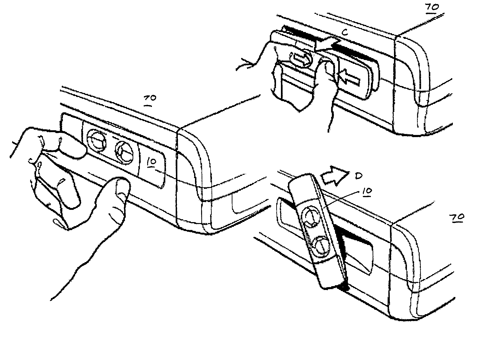
[0070]The right hand portion of FIG. 6 illustrates a design of computer 60 to which the present invention may be usefully applied. As discussed in the preamble to this specification, personal computers including those with small form factors are desirably oriented in a vertical position as shown in FIG. 6. The dimensions of such casing configurations and the mass of the desktop computer units are such that they can be easily tipped over and in cases where the casing cannot be arranged horizontally, some form of vertical stabilization is necessary.

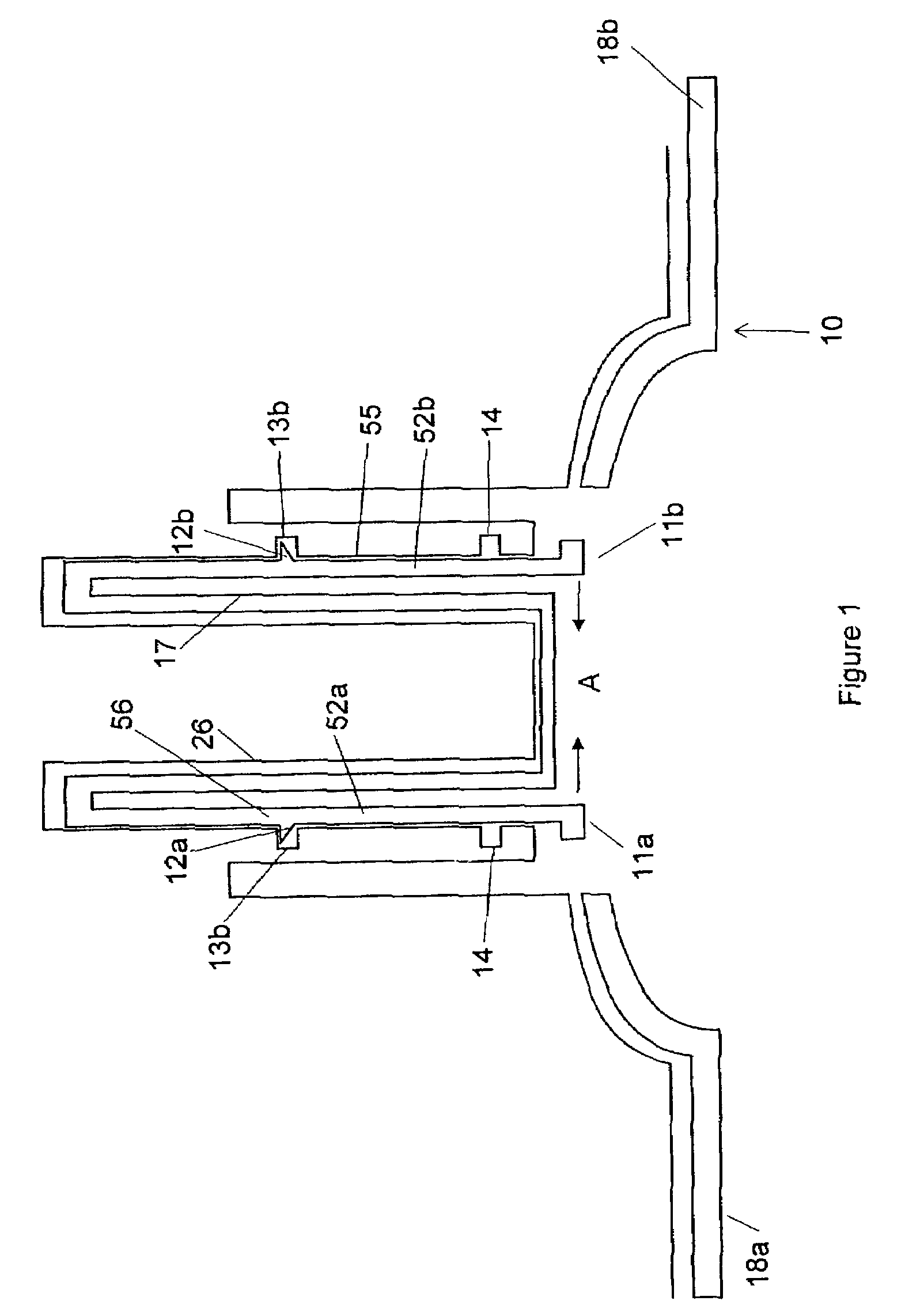
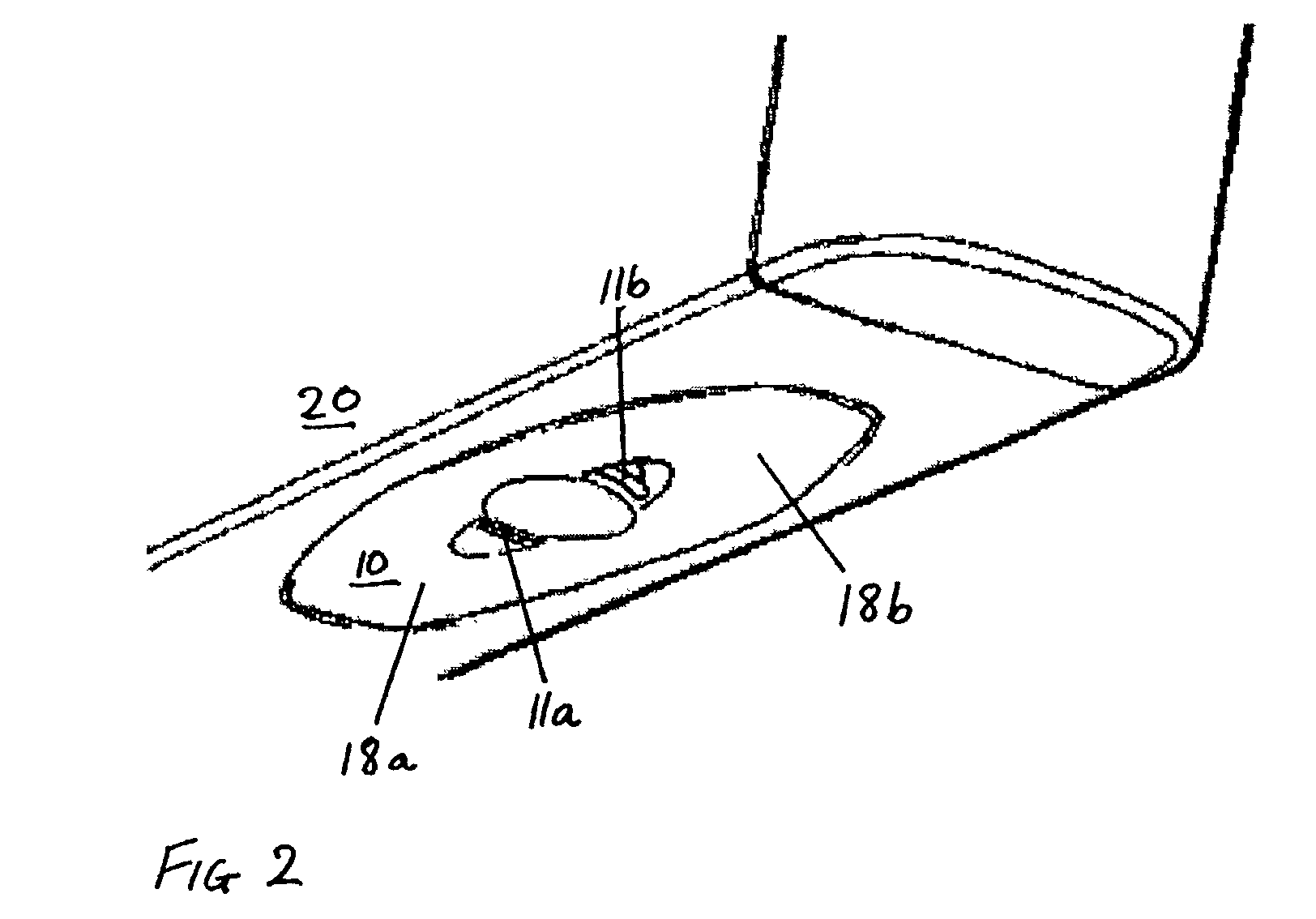
[0071]Referring to FIGS. 2 and 3, a stabilizer 10 in accordance with a preferred embodiment of the invention is shown in the extended (FIG. 3) and retracted (FIG. 2) position. This embodiment corresponds to a simplified and generalized implementation of the present invention and it is noted that refinements including aesthetic and constructional variations are to be considered within the scope of the invention.

[0072]The stabilizer has a gen...


PUM


Abstract

Disclosed is a stabilizing system for a unit having a horizontal and vertical orientation, the chassis cover including at least one wall panel incorporating a recess and a stabilizer adapted to be located in the recess, where the recess is adapted so that in a retracted position the stabilizer is substantially contained within the recess and, in an extended position, the stabilizer extends from the recess in such a way so as to stabilize the chassis when the chassis is mounted in a vertical orientation, wherein the stabilizer is moved into and locked into the extended or stabilizing position by means of a combined extension and rotation action. The stabilizing system may be used to stabilize vertically mounted computer hardware and may be constructed in a variety of ways depending on the style, design, size and type of casing which is to be supported. Partial threads are preferably formed in an engagement portion for positioning the stabilizer in a recess and causing it to automatically position itself in a stabilized position when the locking controls are released.

Description

TECHNICAL FIELD[0001]The present invention relates to apparatus for mounting and / or stabilizing computers and computer related hardware. More particularly, although not exclusively, this invention relates to devices for mounting and / or stabilizing desktop, portable and small form-factor computers in orientations which ensure that necessary operating functions such as cooling etc are not compromised.BACKGROUND ART[0002]Traditional designs for personal computers have evolved from the ‘standard’ personal computer, exemplified by the IBM-AT, to small form-factor PCs such as the e-PC manufactured by Hewlett Packard Company. This design development has resulted in many innovative and creative designs solutions reflecting the acceptance of such hardware in the business and home environment. This evolution in design has also been influenced by aesthetic considerations which were previously considered secondary to the basic task of housing the internal computer hardware in a functional casin...

Claims


Application Information

Patent Timeline
IPC IPC(8): A47B91/00A47B91/02F16M11/00F16M11/10G06F1/18
CPCA47B91/02F16M11/00F16M11/10F16M11/16F16M11/22G06F1/181F16M2200/021F16M2200/08G06F2200/1638Y10S248/917Y10T292/0813
Inventor HELOT, JACQUES HRAHMOUNI, GILBERT
Owner HEWLETT PACKARD DEV CO LP
Learn More