
Impeller and washing machine with impeller

A washing machine and pulsator technology, applied in the field of washing machines, can solve problems such as poor lint collection efficiency, large pressure loss, and poor user experience, and achieve the effects of improving lint collection efficiency, improving component reliability, and reducing pressure loss.

Active Publication Date: 2017-04-05
QINGDAO HAIER WASHING MASCH CO LTD
View PDF9 Cites 14 Cited by
  • Summary
  • Abstract
  • Description
  • Claims
  • Application Information

AI Technical Summary

Problems solved by technology

Moreover, existing designs have many components, poor reliability, and high pressure loss
[0003] During specific work, due to the large amount of water inflow of the pulsator washing machine for washing clothes, generally tens of liters or more, the area of ​​the two lint collectors installed on the inner wall of the pulsator washing machine is relatively small. In this case, only part of the washing water in the washing tub flows through the lint collector, while all the washing water cannot completely circulate through the lint collector, resulting in poor lint collection efficiency of the lint collector, resulting in poor There are still impurities such as lint in the clothes, resulting in a very poor user experience
[0004] Aiming at the above problems in related technologies, no effective solution has been proposed yet

Method used


Image

  • Impeller and washing machine with impeller
  • Impeller and washing machine with impeller
  • Impeller and washing machine with impeller

Examples


Embodiment Construction

[0026] The following will clearly and completely describe the technical solutions in the embodiments of the present invention with reference to the accompanying drawings in the embodiments of the present invention. Obviously, the described embodiments are only some, not all, embodiments of the present invention. All other embodiments obtained by persons of ordinary skill in the art based on the embodiments of the present invention belong to the protection scope of the present invention.

[0027] According to an embodiment of the present invention, a pulsator is provided.

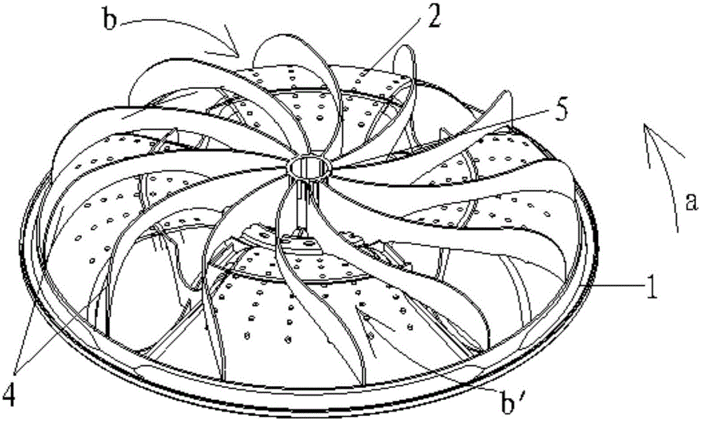
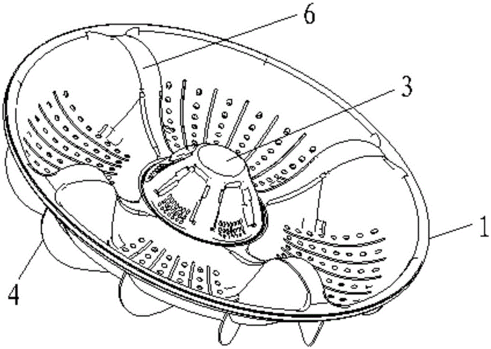
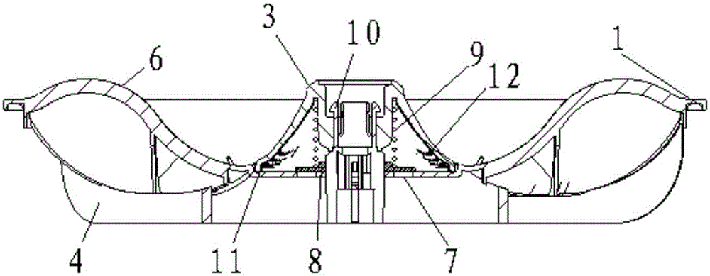
[0028] Such as Figure 1-4 As shown, the pulsator according to the embodiment of the present invention includes a pulsator body 1, a plurality of water permeable holes 2 are arranged on the pulsator body 1, a lint collector 3 is arranged in the middle of the top of the pulsator body 1, and a bottom end of the pulsator body 1 A water flow generating unit is integrally formed, and the water flow generating un...


PUM


Abstract

The invention discloses an impeller and a washing machine with the impeller. The impeller comprises an impeller body, a plurality of water-permeable holes are formed in the impeller body, a line scrap collector is arranged in the middle of the impeller body, and a water flow generation unit is integrally formed at the bottom end of the impeller body. The water flow generation unit comprises a guide unit coaxially arranged on the impeller body, a turbine blade unit arranged on the impeller body with the guide unit as the axis, and a plurality of first through holes symmetrically formed in the bottom of the impeller body and located at the lower end face of the line scrap collector with the guide unit as the axis. A valve is movably arranged at the upper ends of the first through holes. The line scrap collector is arranged at the top end of the impeller, and water at the bottom of the impeller enters the line scrap collector through the guide unit under the rotation action of the impeller. Besides, by means of a movable connection mode using a hinge and a spring, when the impeller body rotates reversely, the valve is closed under the action of the spring, collected line scraps cannot float out along with water flow, and line scrap collection efficiency is improved.

Description

technical field [0001] The invention relates to the technical field of washing machines, in particular to a pulsator and a washing machine with the pulsator. Background technique [0002] At present, the lint collectors of many pulsator washing machines are generally installed inside the inner cylinder of the washing machine. When the washing machine is running, the water flow formed flows through the lint collector as the inner cylinder rotates, and the lint collector collects the lint existing in the water flow. collect. When the washing machine stops running, the lint collector can be removed and cleaned. After the cleaning is completed, the lint collector can be installed back to its original position. Moreover, existing designs have many components, poor reliability, and high pressure loss. [0003] During specific work, due to the large amount of water inflow of the pulsator washing machine for washing clothes, generally tens of liters or more, the area of ​​the two ...

Claims


Application Information

Patent Timeline
IPC IPC(8): D06F17/10D06F39/10
CPCD06F17/10D06F39/10
Inventor 赵志强许升
Owner QINGDAO HAIER WASHING MASCH CO LTD
Learn More