Lift machine

a technology of lifting machine and chassis, which is applied in the direction of lifting frame, lifting device, transportation and packaging, etc., can solve the problems of affecting assembly operation, affecting the stability of the chassis supporting platform, and thereby affecting the tilting of the chassis

Active Publication Date: 2008-02-19
GM GLOBAL TECH OPERATIONS LLC +1
View PDF20 Cites 35 Cited by
  • Summary
  • Abstract
  • Description
  • Claims
  • Application Information

AI Technical Summary

Problems solved by technology

However, stability of the chassis supporting platform becomes an issue when only a single lift actuator is employed.
That moment load can cause tilting of the platform and hence tilting of the chassis.
Such tilting can hinder the assembly operation.

Method used


Image

  • Lift machine
  • Lift machine
  • Lift machine

Examples


Embodiment Construction

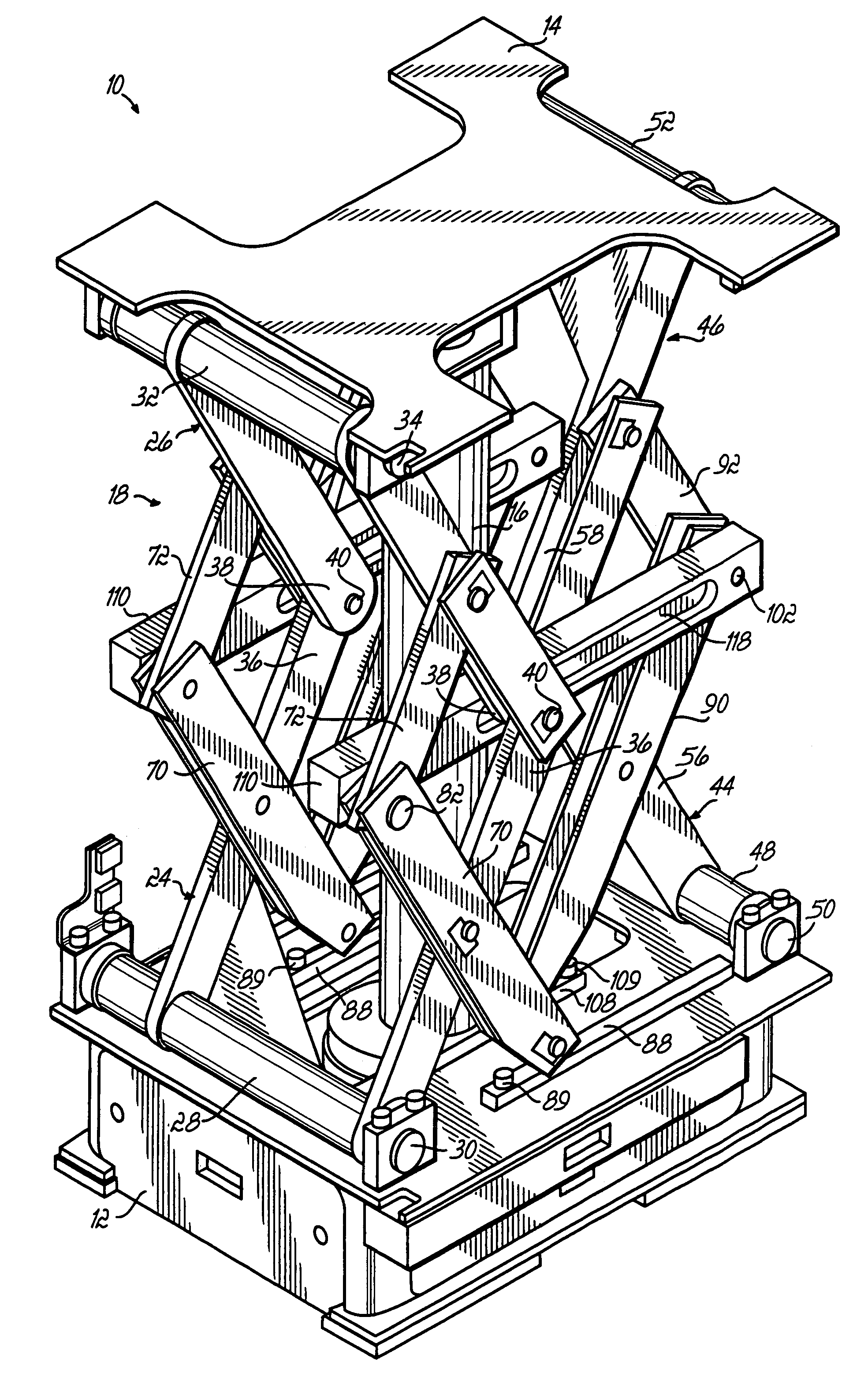
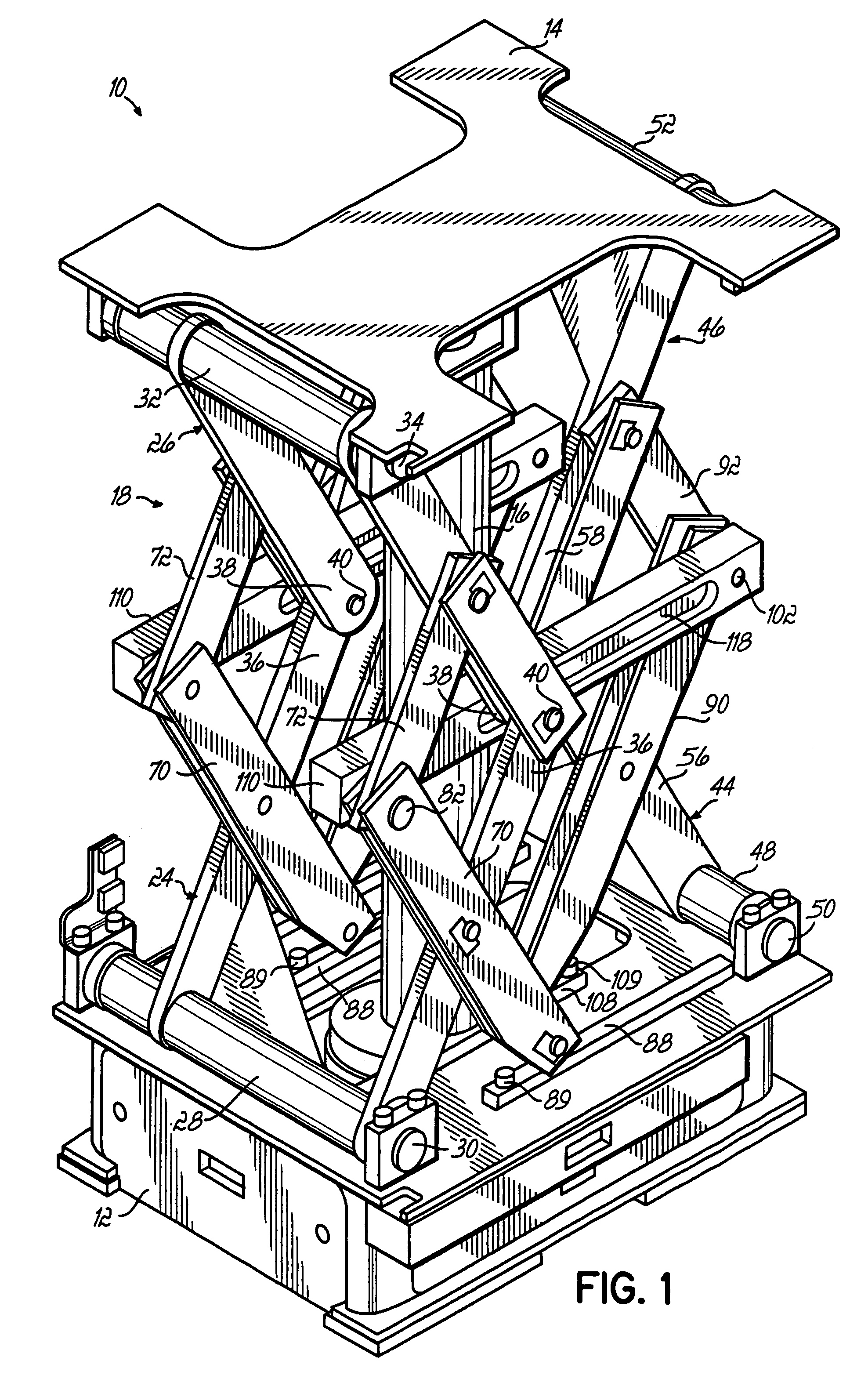
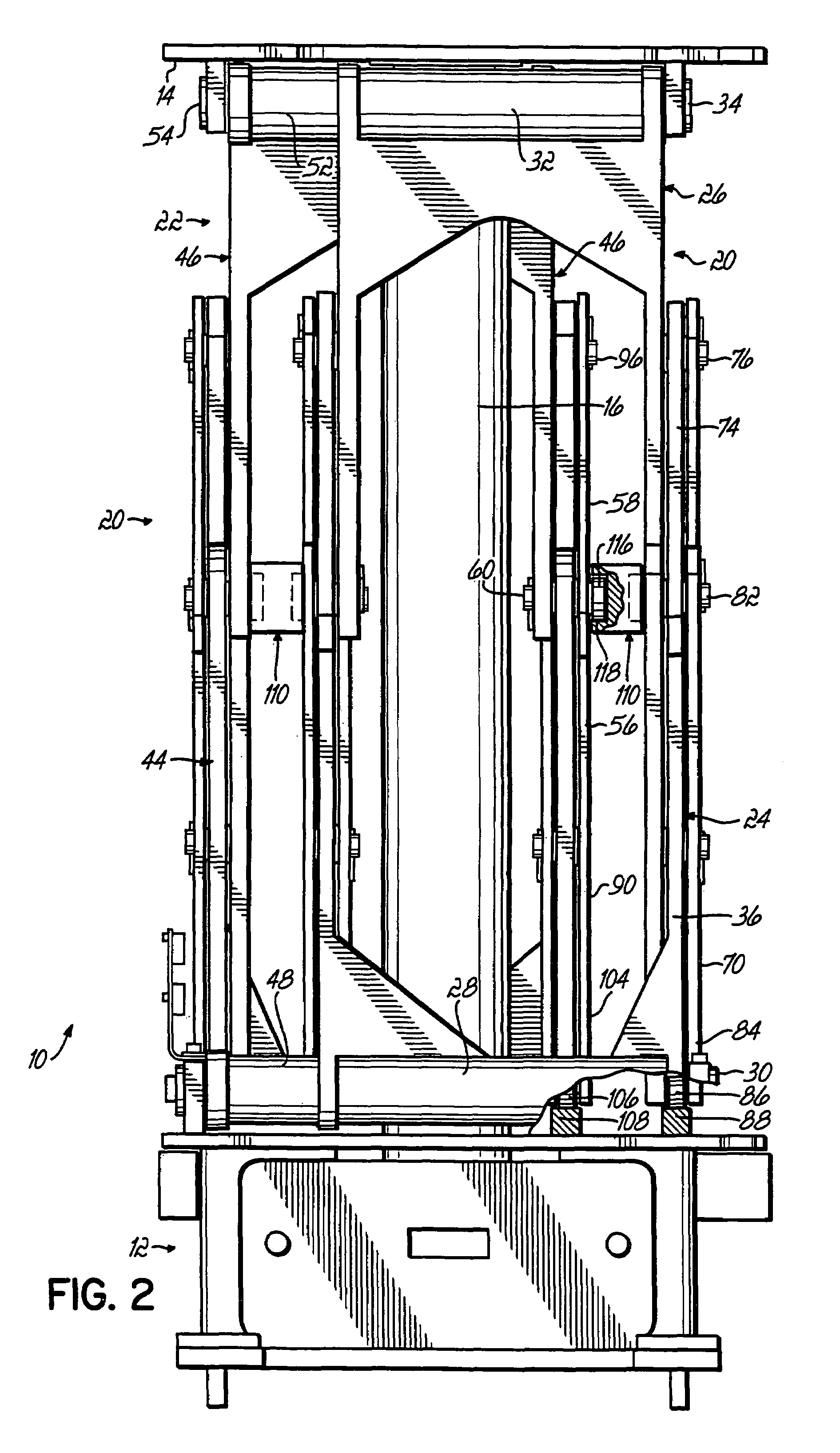
[0021]Referring to FIGS. 1-4, there is illustrated a lift machine 10 according to the present invention. The lift machine 10 has a base 12, a support or platf Referring to FIGS. orm 14 for supporting a load above the base 12, a lift actuator 16 operatively connected between the base 12 and the support 14 for raising and lowering the support 14 relative to the base 12, and a support stabilization mechanism 18 operatively connected between the base 12 and the support 14 for stabilizing the support 14 relative to the base 12 during raising and lowering of the support 14 by the lift actuator 16. Lift actuator 16 can be any suitable lift actuator, for example hydraulic cylinder, push chain (FIG. 3A, 16a), spiral lift (FIG. 38, 16b), air bladder, crank arm, bell crank mechanism, rack and pinion, double rack and pinion, ball screw, telescoping bail screw, roller screw, acme screw, 60° threaded screw, linear or rotary cam, screw jack, electric cylinder, rodless actuator, belt, gear motor ac...


PUM


Abstract

A lift machine comprises a base, a support for supporting a load above the base, a lift actuator operatively connected between the base and the support for raising and lowering the support relative to the base, and a support stabilization mechanism operatively connected between the base and the support for stabilizing the support relative to the base during raising and lowering of the support by the lift actuator. The support stabilization mechanism comprises a pair of opposed linkages, with each of the pair of opposed linkages having a lower torque tube link and an upper torque tube link. The lower torque tube link has a torque tube operatively pivoted to the base. The upper torque tube link has a torque tube operatively pivoted to the support. The pair of opposed linkages are interconnected in such a manner that the pair moves in synchronization during raising and lowering of the support by the lift actuator and maintains the support substantially level even in the event that the center of mass of the load is offset from a vertical axis of the lift actuator.

Description

RELATED APPLICATION[0001]This application is a continuation, and claims the benefit, of provisional patent application Ser. No. 60 / 586,562 filed Jul. 9, 2004, which is hereby incorporated by reference herein as if fully set forth in its entirety.FIELD OF THE INVENTION[0002]This invention relates generally to lift machines, and more particularly to lift machines for use in the automotive vehicle manufacturing industry for lifting a vehicle chassis into place underneath a suspended vehicle body for subsequent fastening of the chassis to the body.BACKGROUND OF THE INVENTION[0003]In the automotive vehicle manufacturing industry, it is customary to “marry” the vehicle chassis to the vehicle body on a moving conveyer line. The body is typically conveyed overhead by a conveyor, and the chassis to be married to the body is supported by a moving lift machine that operates to move the chassis into position beneath the moving body while lifting the chassis into position for assembly with the b...

Claims


Application Information

Patent Timeline
Patent Type & Authority Patents(United States)
IPC IPC(8): B66B9/02B66F3/22B66F7/06
CPCB66F7/18
Inventor BUKOWSKI, LARRYGRIESSER, ANDREWSISTI, VINCENTZIESEL, DETLEV
Owner GM GLOBAL TECH OPERATIONS LLC
Why Eureka
Try Eureka