
Cable connector assembly with wire spacer

a technology of cable connectors and connectors, applied in the direction of coupling device details, coupling device connections, electric discharge lamps, etc., can solve the problems of cable prone to shift to the two halves, high manufacturing cost, and easy trimmed

Inactive Publication Date: 2008-02-19
HON HAI PRECISION IND CO LTD
View PDF7 Cites 12 Cited by
  • Summary
  • Abstract
  • Description
  • Claims
  • Application Information

AI Technical Summary

Benefits of technology

[0008]Accordingly, an object of the present invention is to provide a cable connector assembly having a wire spacer for fixing and orienting wires and making them easy to be trimmed and connected to a circuit substrate or contacts.
[0009]In order to achieve the object set forth, a cable connector assembly in accordance with the present invention comprises an insulative housing, a plurality of contacts received in the insulative housing, a plurality of wires electrically connecting with the contacts, at least a wire spacer defining a plurality of wire receiving cavities along a first direction respectively receiving the wires and at least a window in top surface communicating with the wire receiving cavities, and securing means arranged into the window securely positioning the wires within the wire receiving cavities.

Problems solved by technology

Generally, in high-speed transmission, the signal is transmitted by plural differential pairs with each differential pair containing two wires and it may cause miss-wiring if the pair is in the wrong direction, so a wire spacer is needed to hold and orient the plural wires.
However, the cable holders mentioned foregoing are all made from two parts / halves with plural cavities formed between the parts / halves to receive one row cables therebetween, some problems may occur.
However, there isn't any means to position the cables relative to the other half, thus, when one half assembled, the cables are prone to shift to the two halves.
Secondly, the two-half structure is relatively complex in manufacture and costly in manufacture cost.

Method used


Image

  • Cable connector assembly with wire spacer
  • Cable connector assembly with wire spacer
  • Cable connector assembly with wire spacer

Examples


Embodiment Construction

[0021]Reference will now be made in detail to the preferred embodiment of the present invention.

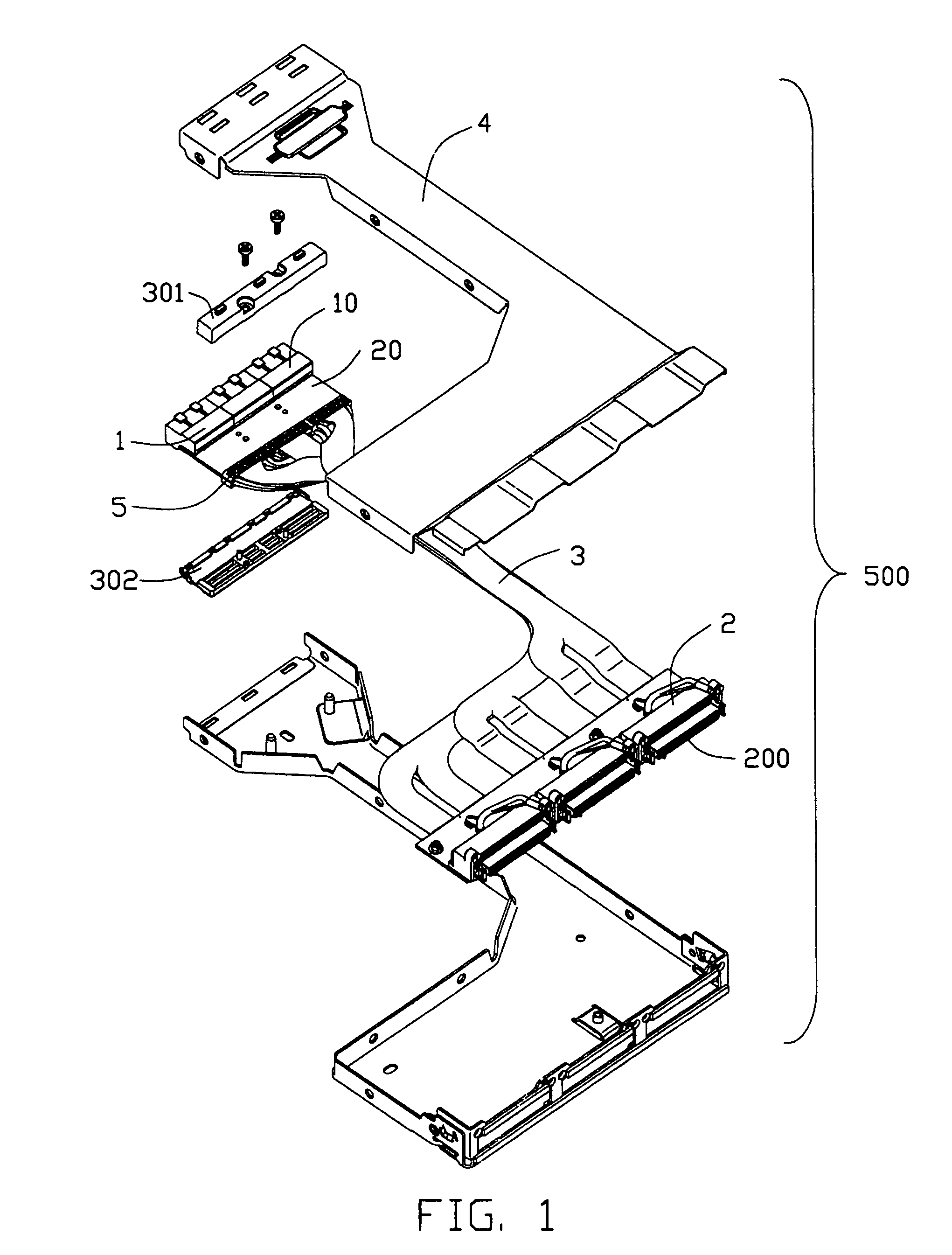
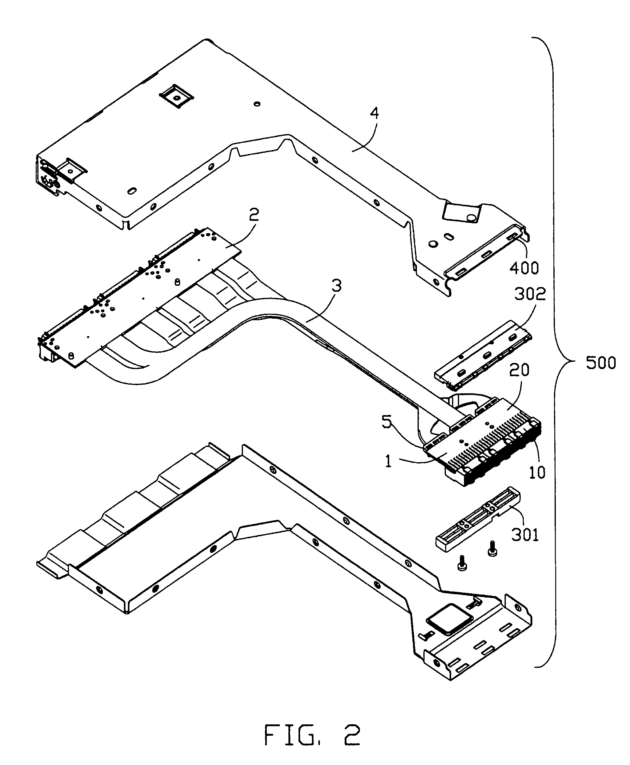
[0022]Referring to FIG. 1 and FIG. 2, a cable connector assembly 500 in accordance with the present invention comprises a first electrical connector 1, a second electrical connector 2, cable means 3 including a plurality of wires 31 (FIG. 6) electrically connected to the first electrical connector 1 and the second electrical connector 2, and a cover 4 forming a space (not shown) to receive the first electrical connector 1, the second electrical connector 2 and the cable means 3.

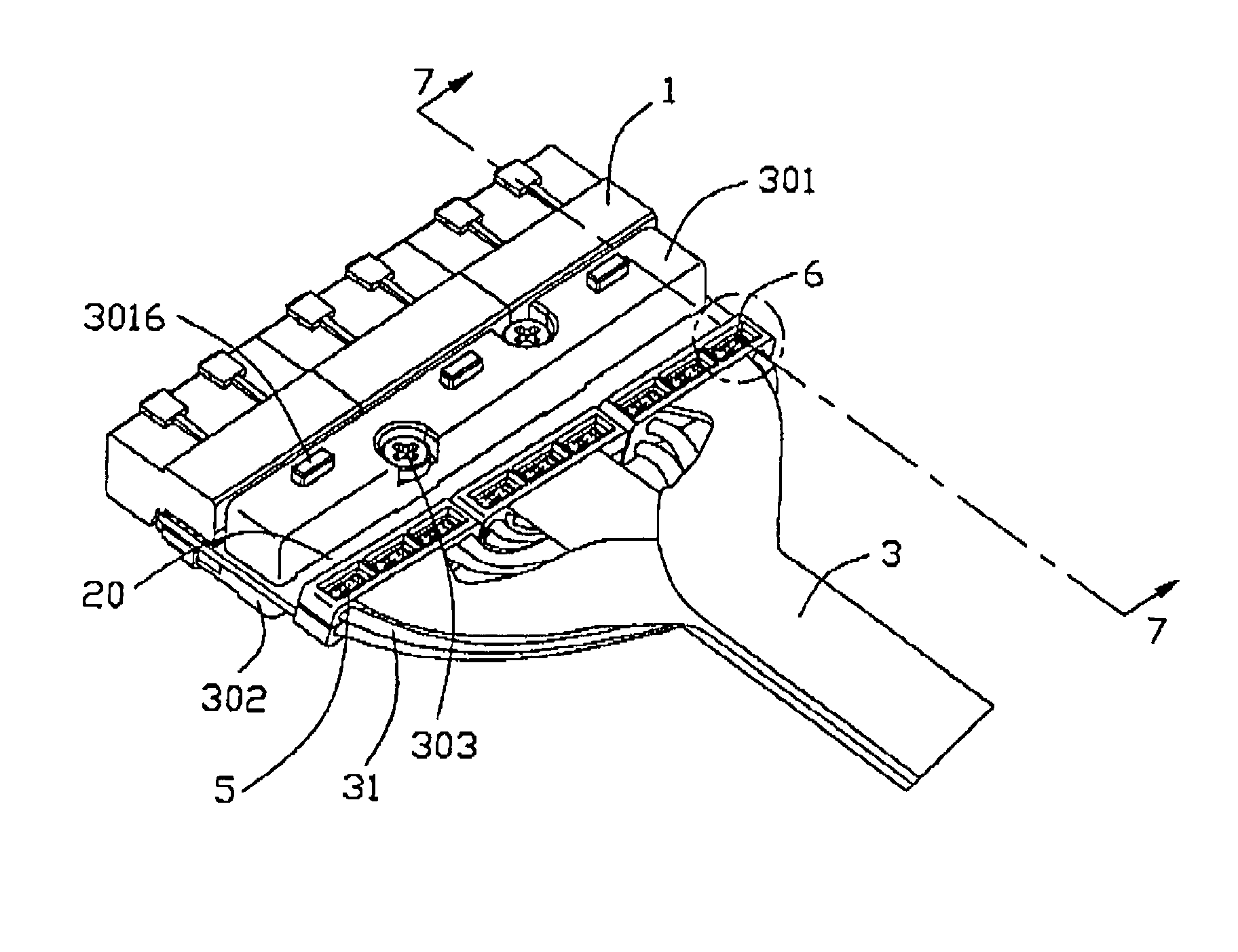
[0023]Referring to FIGS. 3, 4, 6 and 7, the first electrical connector 1 comprises a first connecting module 10, a circuit substrate 20 having circuit traces (not shown) formed thereon electrically connecting to the first connecting module 10, a reinforcing member 301 / 302 assembled to the circuit substrate 20 and a plurality of wire spacers 5 used for fixing and orienting the wires 31 of the cable means 3. The firs...


PUM


Abstract

An cable connector assembly (500) for high-speed transmission includes a first electrical connector (1) defining a first mating port, a second electrical connector (2) defining a second mating port different from the first mating port (100), cable means (3) electrically connected to the first electrical connector (1) and the second electrical connector (2), and a plurality of wire spacers (5) used for fixing the wires of cable means (3) so as to trim and solder them easily.

Description

CROSS-REFERENCE TO RELATED APPLICATION[0001]This application is a continuation-in-part (CIP) of U.S. patent application Ser. No. 11 / 144,114 filed on Jun. 3, 2005 now U.S. Pat. No. 7,128,614, invented by Jerry Wu, entitled “ELECTRICAL ADAPTER WITH REINFORCING MEMBER”, which is assigned to the same assignee as this application.BACKGROUND OF THE INVENTION[0002]1. Field of the Invention[0003]The present invention generally relates to a cable connector assembly, and more particularly to a cable connector assembly used for high speed transmission.[0004]2. Description of Related Art[0005]A cable connector assembly usually includes a cable including some discrete wires arranged in a side-by-side manner with relative high-density and at least an electrical connector connecting with the wires. The cable connector assembly generally comprises a spacer / cable holder / cable organizer for holding cables / wires to make it easy to trim and connect cables / wires to the electrical connecter. U.S. Pat. No...

Claims


Application Information

Patent Timeline
Patent Type & Authority Patents(United States)
IPC IPC(8): H01R27/02
CPCH01R13/6658H01R31/06
Inventor LIN, YUAN-CHIEH
Owner HON HAI PRECISION IND CO LTD
Learn More