Stripping apparatus and process

a technology of fluidized contact and stripping apparatus, which is applied in the direction of lighting and heating apparatus, synthetic resin layered products, furnaces, etc., can solve the problems of increasing the risk of clogging, large surface area of the particles employed in the fcc process, and significant amount of hydrocarbons being withdrawn from the reaction zone with the catalys

Active Publication Date: 2008-02-19
UOP LLC
View PDF21 Cites 26 Cited by
  • Summary
  • Abstract
  • Description
  • Claims
  • Application Information

AI Technical Summary

Benefits of technology

[0013]It has now been found that providing a structural packing comprising ribbons with angular bands and openings between adjacent edges to allow catalyst flow can be uniformly installed into a stripping vessel with relatively small occasion of clogging by spalling coke deposits. The structural packing of the present invention can be installed in a stripping vessel with or without an internal riser. We have found that the structural packing of the present invention can provide stripping performance very close to ideal stripping models.

Problems solved by technology

However, the catalyst particles employed in an FCC process have a large surface area, which is due to a great multitude of pores located in the particles.
Although the quantity of hydrocarbons retained on each individual catalyst particle is very small, the large amount of catalyst and the high catalyst circulation rate which is typically used in a modern FCC process results in a significant quantity of hydrocarbons being withdrawn from the reaction zone with the catalyst.
Byproduct coke in FCC units have been known to accumulate in relatively unfluidized zones to spall off in large pieces during abrupt changes in conditions to clog narrow flow channels.
Hence, structured packings in an FCC unit with narrow flow channels would increase the risk of such clogging.
Otherwise, poor distribution of catalyst and stripping gas flow may generate non-uniform vapor-solids contact which can diminish stripping performance.
Uniformly installing structured packings with intersecting planar members in stripping devices with round inner walls can be difficult requiring intense labor.
Therefore, the theoretical amount of stripping gas for a perfect counter-current stripper model becomes the low limitation for design of a stripper.

Method used


Image

  • Stripping apparatus and process
  • Stripping apparatus and process
  • Stripping apparatus and process

Examples


example 1

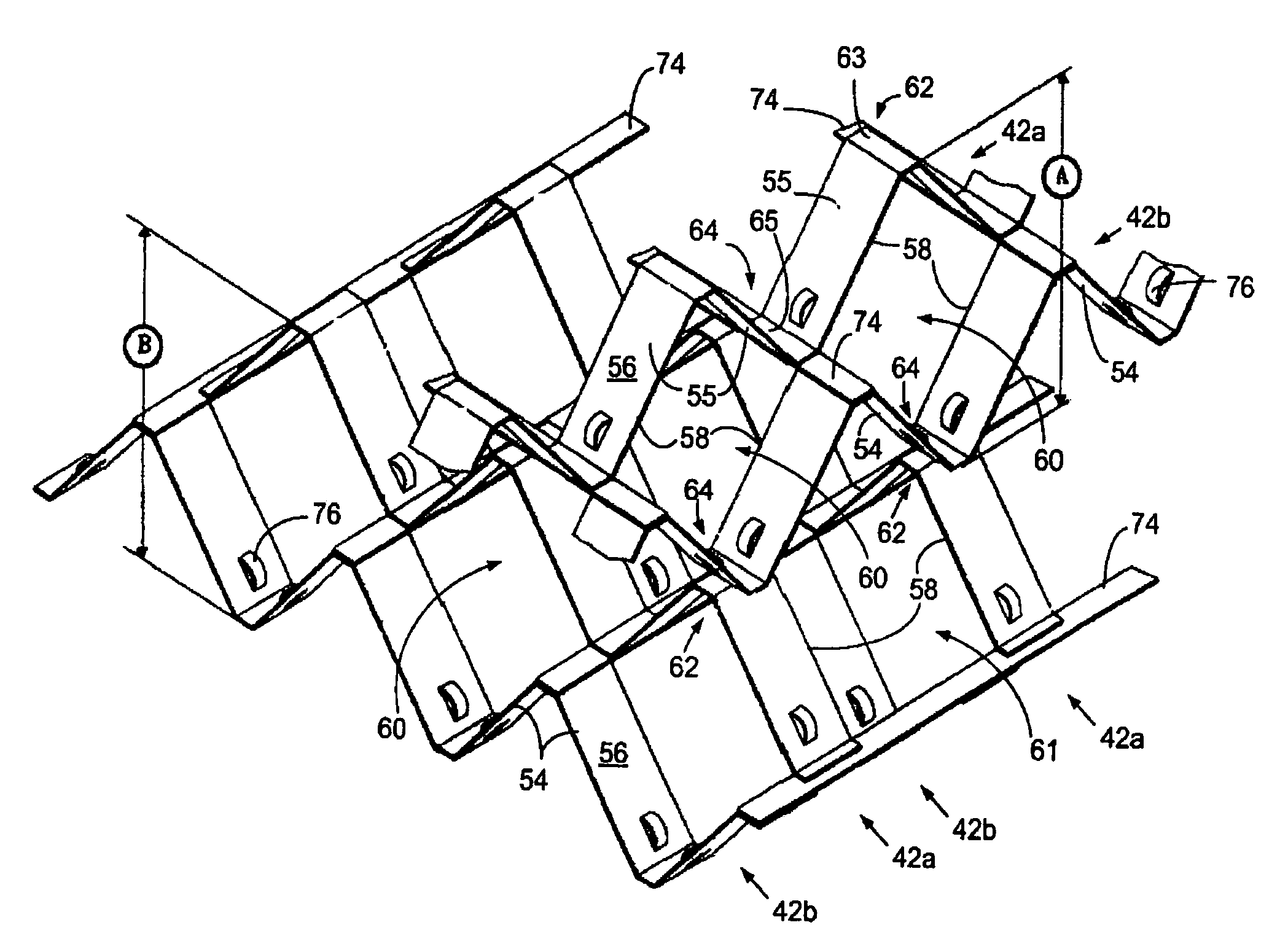
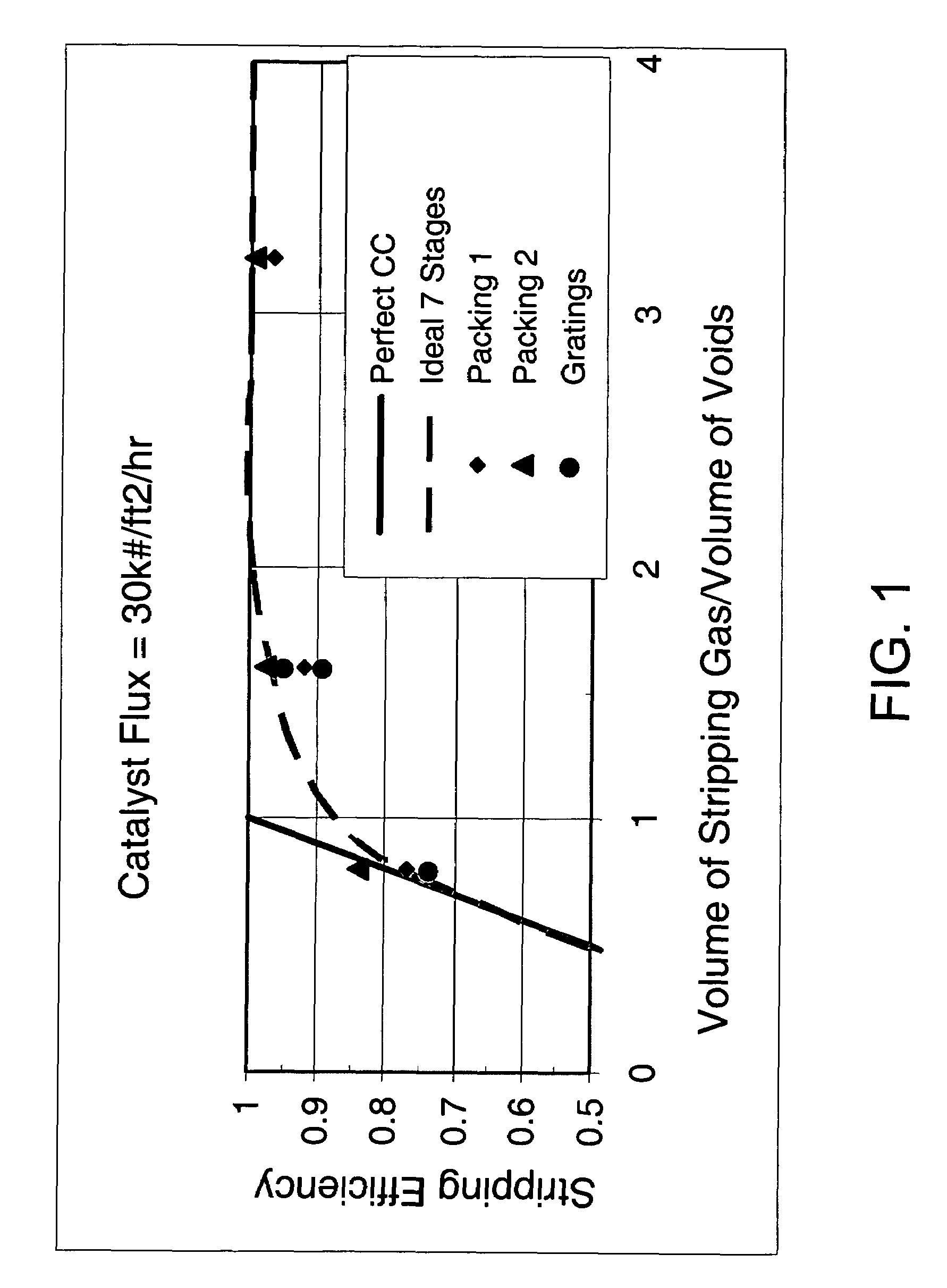
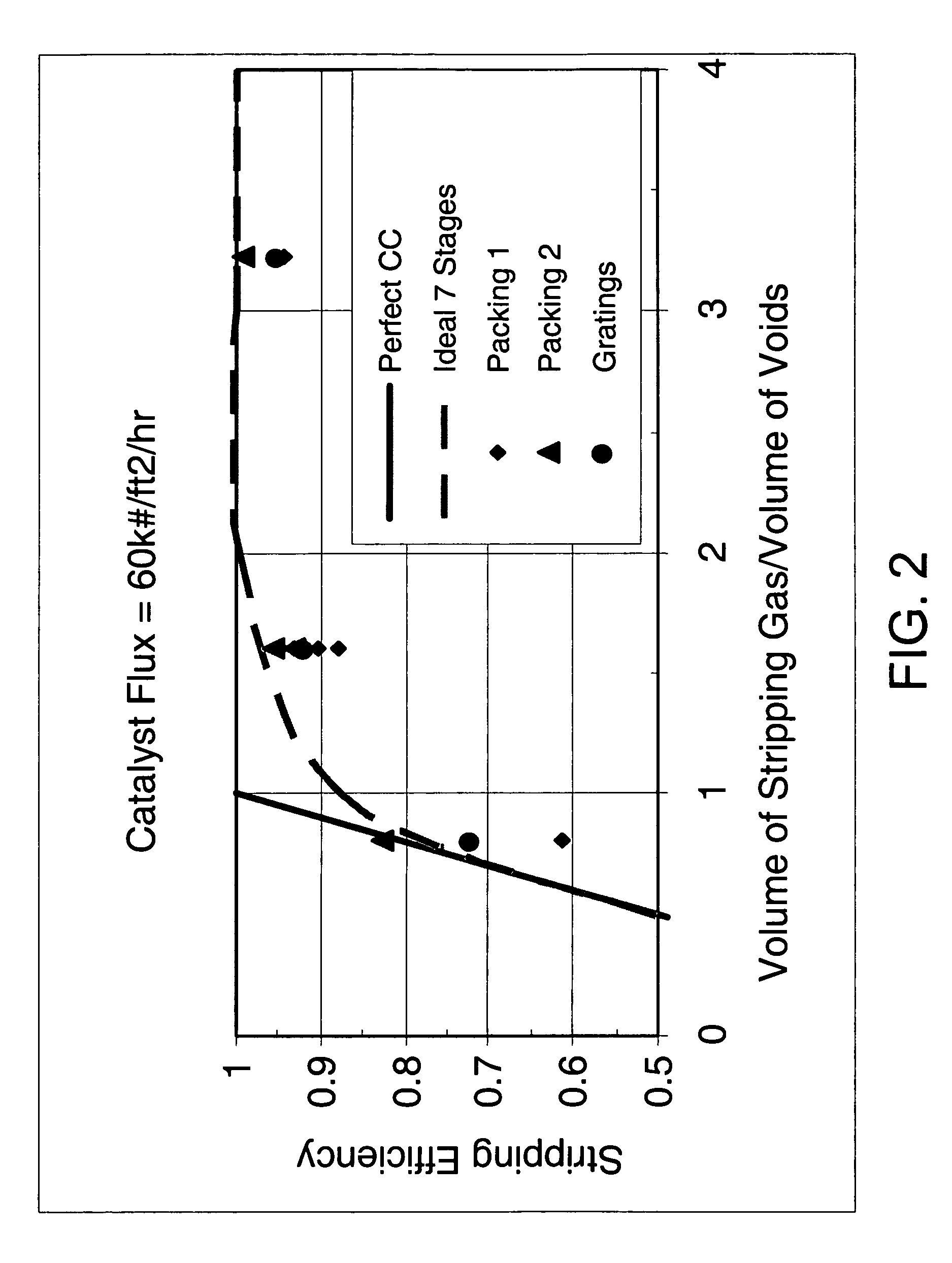
[0041]The stripper embodiments of the present invention were evaluated for performance relative to ideal stripping performance. We constructed a test apparatus embodying the stripping arrangements of the present invention as shown in FIGS. 5-7, labeled Packing 1, and FIGS. 8-12, labeled Packing 2. The test apparatus comprised a cylinder having a 0.6 m (2 foot) diameter. Packing 1 occupied a vertical height of 2.3 m (7.5 feet) and Packing 2 occupied 2.2 m (7.2 feet). Overall, the height of the cylinder was 8 m (26.3 feet). The test apparatus was operated by circulating equilibrium FCC catalyst downwardly from a top inlet through the apparatus while air passed under the lowermost baffle upwardly through the baffles. The recovery of adsorbed hydrocarbons was simulated by injection of helium tracer into the circulating catalyst followed by measurement of the helium concentration in the recovered air. The stripped catalyst was recovered from the bottom of the test apparatus and the conce...


PUM

PropertyMeasurementUnit
boiling pointsaaaaaaaaaa
temperatureaaaaaaaaaa

Abstract

An apparatus and process for stripping gases from solids comprises a structured packing in a stripping section of a vessel. The structured packing comprises a plurality of corrugated ribbons with each corrugated ribbon having at least two faces angular to each other. The ribbons at least partially obstruct passage of the solid particles. Edges of adjacent ribbons defining openings for the passage of contacted particles.

Description

BACKGROUND OF THE INVENTION[0001]This invention relates to processes and apparatus for the fluidized contacting of catalyst with hydrocarbons. More specifically, this invention relates to an apparatus and process for stripping entrained or adsorbed hydrocarbons from catalyst particles.DESCRIPTION OF THE PRIOR ART[0002]A variety of processes contact finely divided particulate material with a hydrocarbon containing feed under conditions wherein a fluid maintains the particles in a fluidized condition to effect transport of the solid particles to different stages of the process. Fluid catalytic cracking (FCC) is a prime example of such a process that contacts hydrocarbons in a reaction zone with a catalyst composed of finely divided particulate material. The hydrocarbon feed fluidizes the catalyst and typically transports it in a riser as the catalyst promotes the cracking reaction. As the cracking reaction proceeds, substantial amounts of hydrocarbon, called coke, are deposited on the...

Claims


Application Information

Patent Timeline
Patent Type & Authority Patents(United States)
IPC IPC(8): B32B5/02B32B27/04B01J8/04B01J8/18B01J8/34B01J19/32C10G11/18
CPCC10G11/18
Inventor HEDRICK, BRIAN W.XU, ZHANPINGPALMAS, PAOLOKOWALCZYK, MITCHELL J.WESTBY, MATTHEW J.GU, WEIKAIHOUDEK, J. MARKMONKELBAAN, DANIEL R.
Owner UOP LLC
Why Eureka
Try Eureka