Device for screwing caps onto receptacles

a technology for screwing caps and receptacles, which is applied in the direction of caps, closures using caps, closures, etc., can solve the problems of premature wear of clamps and run the risk of scratching caps, and achieve the effect of simple and inexpensiv

Inactive Publication Date: 2008-02-26
SERAC GROUP
View PDF21 Cites 22 Cited by
  • Summary
  • Abstract
  • Description
  • Claims
  • Application Information

AI Technical Summary

Benefits of technology

[0003]An object of the invention is to provide means that are simple and inexpensive for adjusting the clamping torque of caps and for stopping rotation of the spindle.BRIEF SUMMARY OF THE INVENTION
[0007]The structure of the device, and more particularly of the displacement member, is thus particularly simple.
[0009]Changing the height adjustment of the cam relative to the structure serves to modify the depth to which the core is engaged in the bell. It is thus possible to adjust the tightening torque, i.e. the maximum value of the torque that can be transmitted between the bell and the core. This is particularly advantageous when a plurality of rotary spindles are mounted on the platform, since a single action adjusting the height of the cam serves to modify the value of the tightening torque for all of the spindles.

Problems solved by technology

Opening the clamp while torque is being exerted thereon thus runs the risks of scratching the cap and of wearing the clamp prematurely.

Method used


Image

  • Device for screwing caps onto receptacles
  • Device for screwing caps onto receptacles
  • Device for screwing caps onto receptacles

Examples


Embodiment Construction

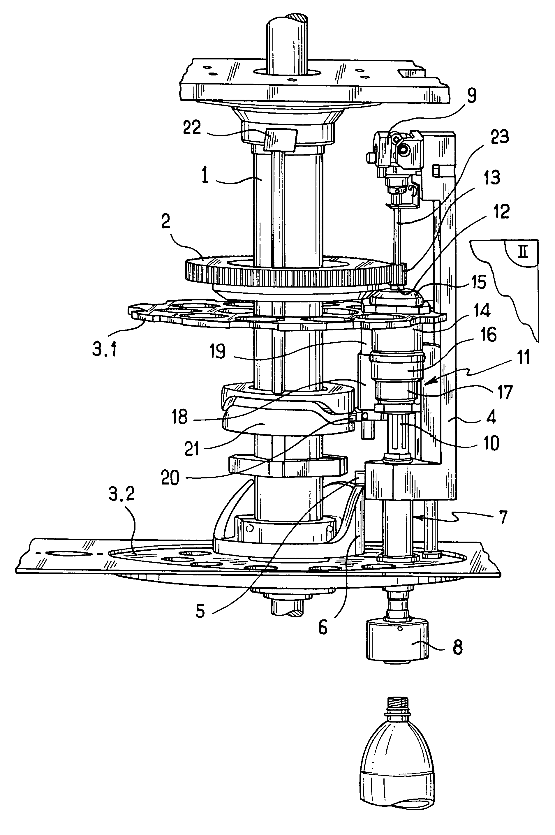
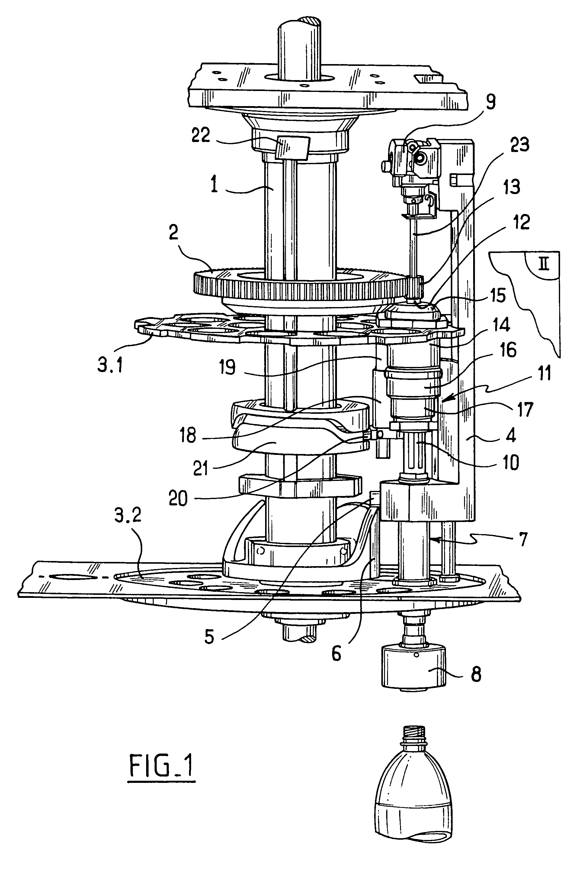
[0015]The cap-tightener device in accordance with the invention comprises a stationary structure 1 having a tube provided with a stationary toothed ring 2, and a platform 3 mounted on the stationary structure 1 to turn about the toothed ring 2. The platform 3 is driven by a drive shaft turning in the tube of the stationary structure 1 and it comprises two plates, namely a top plate 3.1 and a bottom plate 3.2 that are parallel and that are held spaced apart from each other by spacer-forming columns (not shown in the figures).

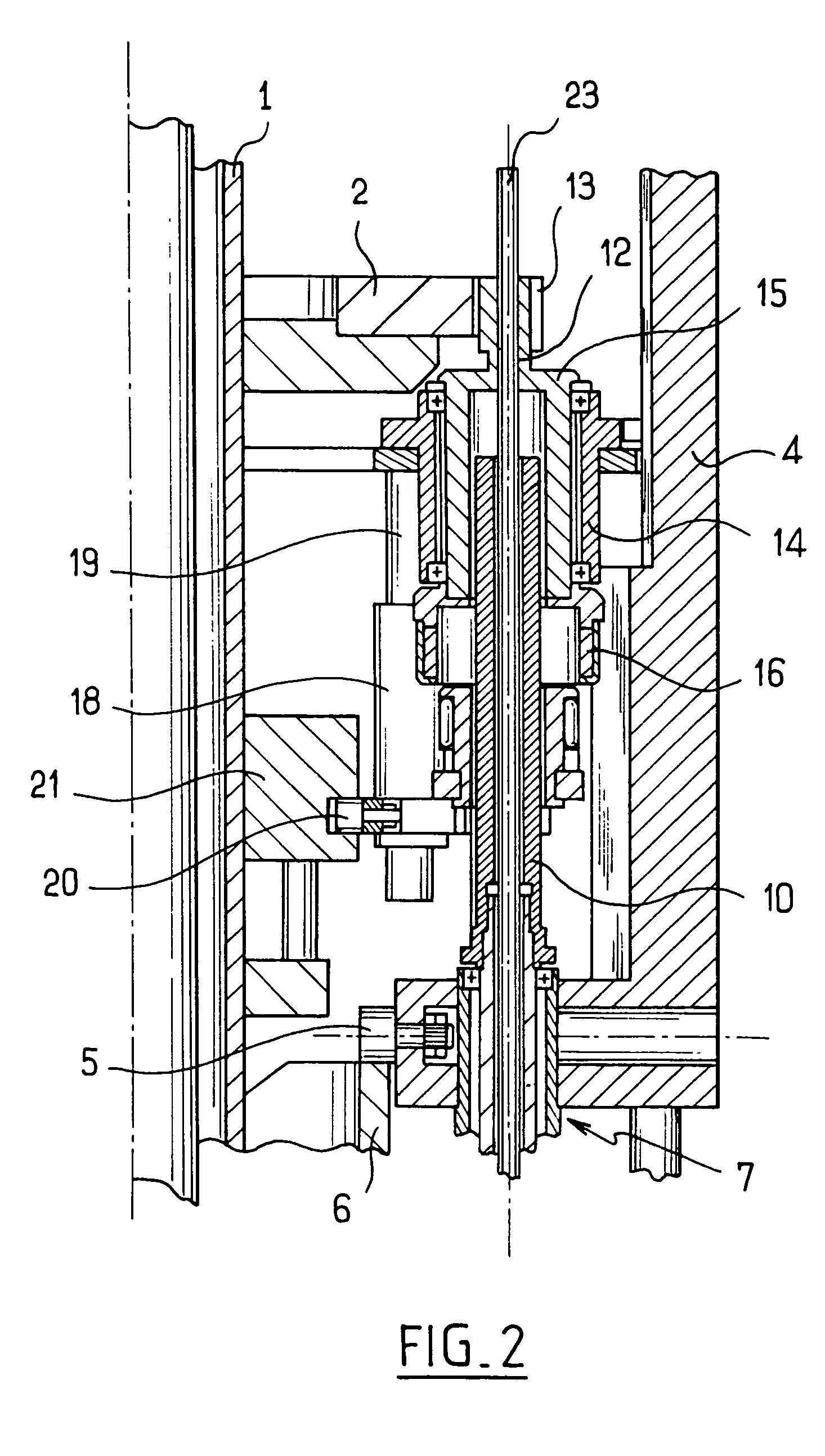
[0016]The platform 3 is fitted with vertical support elements 4 mounted in conventional manner to slide parallel to the axis of rotation of the platform 3. Each support element 4 is fitted with a wheel 5 running on a cam 6 that is stationary relative to the structure 1 and disposed coaxially about the axis of the platform 3 so as to move the support element 4 between a high, rest position (shown in FIG. 1) and a low, end-of-tightening position (shown in FIG. 3).

[...


PUM


Abstract

A device for screwing caps onto receptacles, the device comprising a rotary spindle having a first end provided with a cap gripper head and a second end connected to a two-portion clutch member, one of which portions is constrained to rotate with the second end of the rotary spindle, and the other of which portions is constrained to rotate with a drive shaft on the same axis as the spindle and associated with a drive member, wherein the portions of the clutch member comprise a magnetic bell and a magnetic core having dimensions suitable for enabling it to be engaged in the bell, the device further comprising a displacement member for displacing the bell and the core relative to each other between a position in which the core is engaged in the bell and a position in which the core is disengaged from the bell.

Description

[0001]The present invention relates to a device for screwing caps onto receptacles.BACKGROUND OF THE INVENTION[0002]A device for screwing on caps generally comprises a stationary structure, a platform mounted to pivot on the stationary structure, and rotary spindles mounted on the platform. Each rotary spindle has a first end provided with a head for gripping caps, and a second end connected via a torque limiter to a drive shaft having a gearwheel meshing with a toothed wheel secured to the stationary structure. There exist magnetic torque limiters comprising a magnetic bell constrained to rotate with the drive shaft and a magnetized magnetic core constrained to rotate with the spindle and slidably received in the bell so that the bell and the core are coupled together magnetically. The depth to which the core is engaged in the bell determines the maximum torque that can be transmitted from the bell to the core, and thus the tightening torque. At the end of screw tightening, the gri...

Claims


Application Information

Patent Timeline
Patent Type & Authority Patents(United States)
IPC IPC(8): B65B7/28B67B3/20
CPCB67B3/2033B67B3/2086
Inventor BRUNEE, JACKY
Owner SERAC GROUP
Why Eureka
Try Eureka