Eureka AIR delivers breakthrough ideas for toughest innovation challenges, trusted by R&D personnel around the world.

Automatically deployable boom extension and method of deploying same

Active Publication Date: 2008-03-04
MANITOWOC CRANE CO LLC
View PDF14 Cites 9 Cited by
  • Summary
  • Abstract
  • Description
  • Claims
  • Application Information

AI Technical Summary

Problems solved by technology

While this arrangement performs satisfactorily, if an operator inadvertently removes the safety retaining pin from the intermediate support, pulling the rear portion of the boom extension away from the boom could result in the entire boom extension detaching from the boom and severely injuring the operator.
Even with relatively small cranes, however, it is difficult for an operator to move the heavy boom extension as required to ensure that the front end of the boom extension is aligned with openings on the boom.
This arrangement has therefore not been widely adopted on small cranes and is impracticable for larger cranes having heavier boom extensions.

Method used


Image

  • Automatically deployable boom extension and method of deploying same
  • Automatically deployable boom extension and method of deploying same
  • Automatically deployable boom extension and method of deploying same

Examples


Embodiment Construction

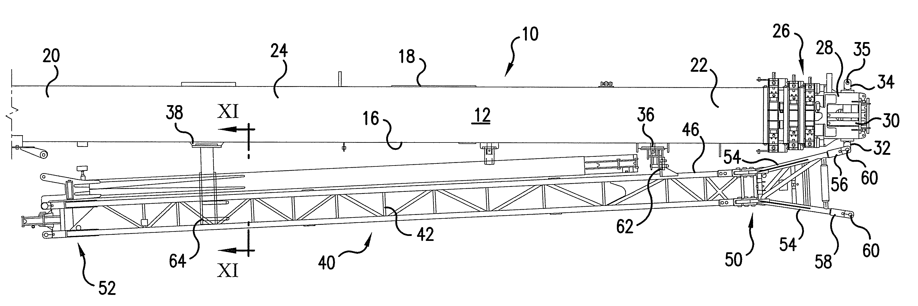
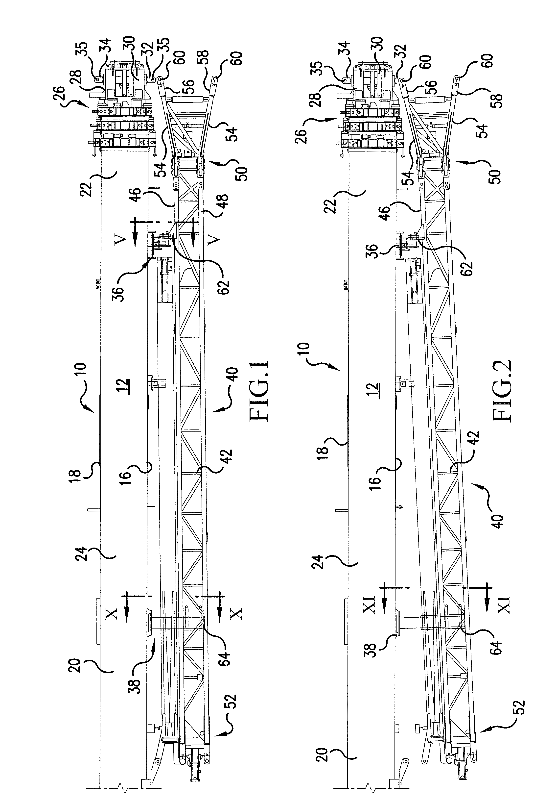
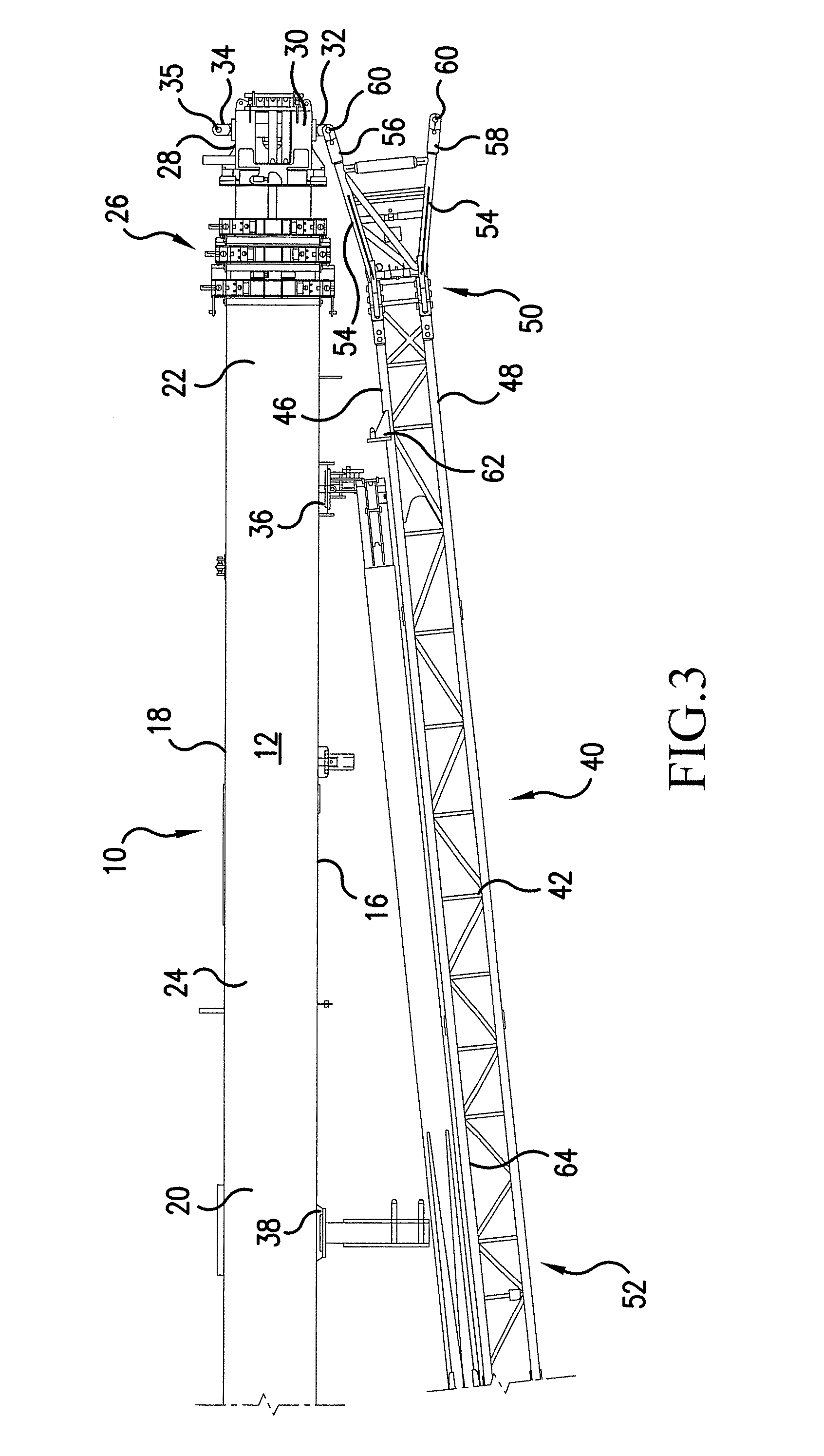
[0027]Referring now to the drawings, which are for purposes of illustrating preferred embodiments of the invention only and not for the purpose of limiting same, FIGS. 1-4 and 17 illustrate a boom 10 having a top 12, a bottom 14 a first side 16, a second side 18, a rear end 20 and a front end 22. Boom 10 further comprises a base section 24 and a plurality of telescoping sections 26 projecting from front end 22. The telescoping end of the boom may be referred to hereinafter as the front of the boom and the opposite end of the boom may be referred to as the rear or base of the boom. These terms will also be used to describe the boom extension mounted on the side of the boom; that is the “front” of the boom extension is the portion closest to the telescoping portion of the boom when the extension is mounted on the boom even though the front and rear portions of the boom extension will change position as the boom extension swings into its use position (see, e.g. FIG. 17). Relative direc...


PUM


Abstract

A crane including a telescoping boom has a base boom member and an inner member slidably mounted in the base boom member with a first end projecting from the base boom member. The inner member includes first and second connector elements. A boom extension has a first end including first and second attachment elements. The boom extension also includes first and second spaced bracket assemblies and is shiftable between use and storage positions. A first support associated with the base boom member includes a holder for pivotably retaining the first bracket assembly and a second support has a rail projecting from the base section. A slider is slidably supported by the rail, and an actuator connected between the slider and the boom shifts the slider between a retracted position and an extended position relative to the base boom member. A method of deploying a boom extension is also disclosed.

Description

FIELD OF THE INVENTION[0001]The present invention is directed toward an automatically deployable boom extension and to a method of deploying same, and, more specifically, toward a boom having an actuator connected thereto for moving a portion of a boom extension away from the boom during a boom extension deployment and toward a method of controlling the actuator during the course of a boom extension deployment.BACKGROUND OF THE INVENTION[0002]To extend the reach of crane booms having telescopic boom sections, a side stowable jib or boom extension may be provided for connection to the nose assembly of the fly section or next adjacent boom section, as disclosed in U.S. Pat. Nos. 3,785,505, dated Jan. 15, 1974, and 4,483,447, dated Nov. 20, 1984. The entire contents of these patents are hereby incorporated by reference.[0003]When moving the boom extension from a storage position on the side of the telescopic boom to a use position wherein the boom extension extends outwardly in alignme...

Claims


Application Information

Patent Timeline
IPC IPC(8): B66C23/42
CPCB66C23/42B66C23/702
Inventor HULL, WILLIAM E.
Owner MANITOWOC CRANE CO LLC
Why Eureka
Eureka Blog
Learn More