Footwear with independent suspension and protection

a technology of independent suspension and protection, applied in the direction of fastenings, uppers, bootlegs, etc., can solve the problems of instability and motion control, bruising and risk of injury, and the midsole allows the heel to move into the midsole, so as to reduce instability

Inactive Publication Date: 2007-09-13
JABIL CIRCUIT INC
View PDF26 Cites 122 Cited by
  • Summary
  • Abstract
  • Description
  • Claims
  • Application Information

AI Technical Summary

Benefits of technology

[0019] A further embodiment of the present invention relates to an article of footwear for use by a wearer having an upper member operable to engage a foot of the wearer and a sole connected to the upper member. The sole includes a plurality of stability members operable to engage a ground surface and to cantilever independently in response to ground forces so as to provide stability for the wearer. A first one of the plurality of stability members may cantilever in response to a first object, and a second one of the plurality of stability members may cantilever in response to a second object.
[0020] A still further embodiment of the present invention relates to an article of footwear for use by a wearer including a sole having a plurality of discreet, resilient stability members for contacting a ground surface. The stability members are operable to absorb forces and attenuate instability caused by irregularities in the ground surface. Each of the stability members may define a ground contacting portion, wherein the stability members each have a predetermined maximum depth of compression, and wherein the stability members attenuate instability by independently compressing up to the maximum depth of compression such that the ground contacting portions thereof contour to the ground surface. The stability members may reduce instability by attenuating inversion and eversion of the ankle joint of the wearer.

Problems solved by technology

This causes the wearer to absorb much of the force and impact of any uneven terrain underfoot, leading to instability, bruising and risk of injury, including for example, the turning of an ankle.
A common problem in footwear, in particular athletic footwear, is that although a softer midsole is desirable for absorption of ground forces, too soft of a midsole allows the heel to displace into the midsole under load conditions.
Excessive displacement of the heel often leads to overpronation, causing instability and motion control issues.
In this arrangement, when an object is stepped on or when uneven terrain is encountered, the hard outsole causes the bottom portion of the shoe to react as a unitary structure and often leads to instability when in contact with uneven surfaces.
This also reduces the amount of ground contact for the shoe, which can cause traction problems.
Furthermore, such a design leads to problematic levels of point loading when objects are encountered.
Point loading can cause the portion of the sole with which the foot makes contact (typically an insole) to deflect upwardly into the foot, which can cause pain and discomfort for the wearer.
This can also cause bruising under foot and can adversely affect whole body stability of the wearer.
Problems with stability and point loading are particularly prevalent in what is generally known as trail running.
When an object or uneven terrain causes pronation or supination to increase beyond the average maximum range for a given subject, instability begins to occur.
By further example, if the rear foot angle begins to approach a pronation angle of about 30 degrees, excess motion of the hip can occur, which results in movement of the pelvis.
Excess movement of the ankle, knee and hip joints may result in upper body instability.
Instability contributes to loss of control or balance.
Current footwear does not adequately address such trail running requirements.
These structures may also be beneficial for other forms of conventional running or hiking and in other situations, where objects may also be encountered and inclement conditions can cause problems relating to stability, traction and comfort.

Method used


Image

  • Footwear with independent suspension and protection
  • Footwear with independent suspension and protection
  • Footwear with independent suspension and protection

Examples


Embodiment Construction

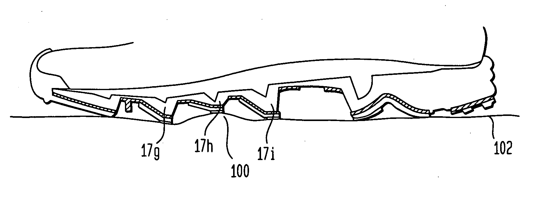
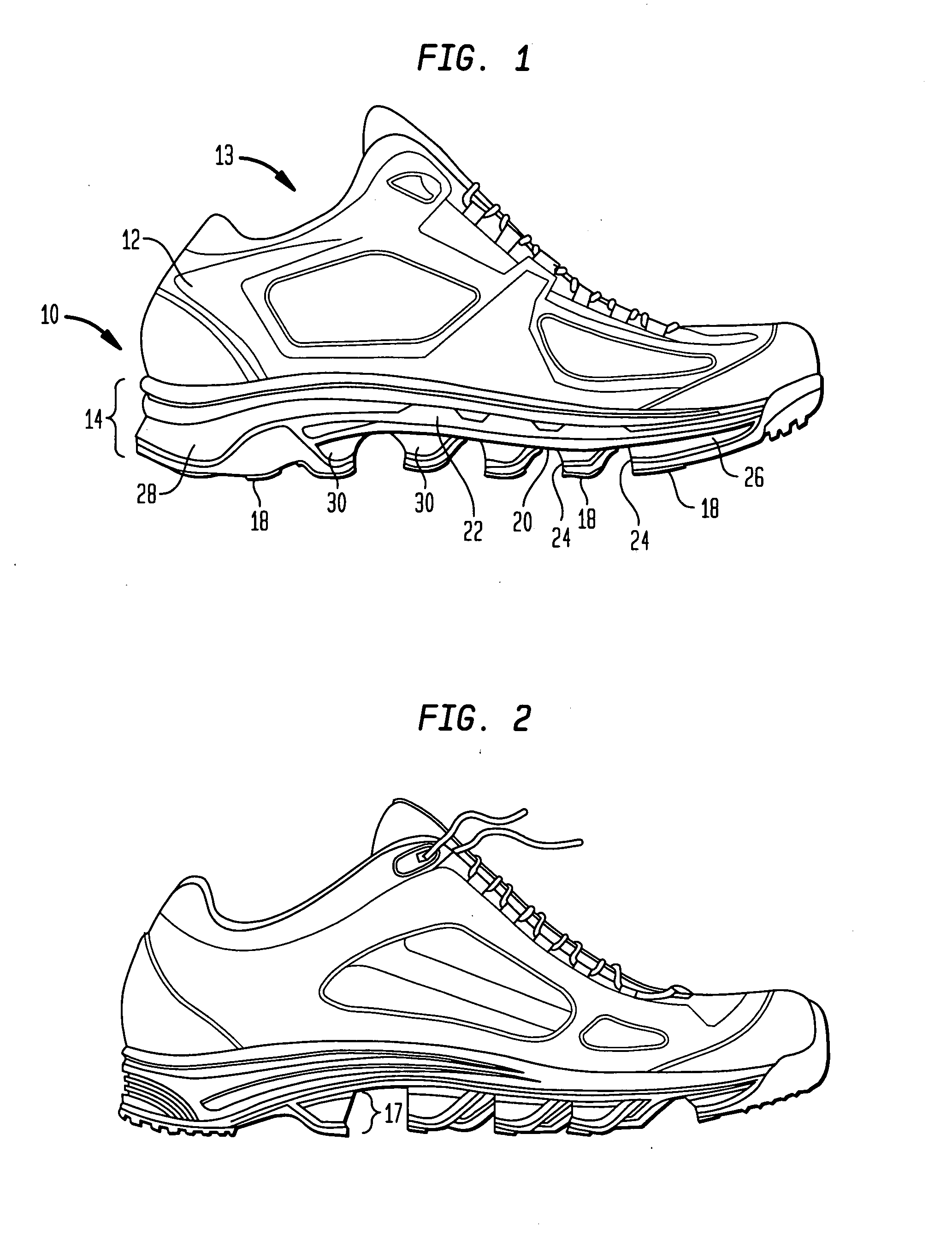
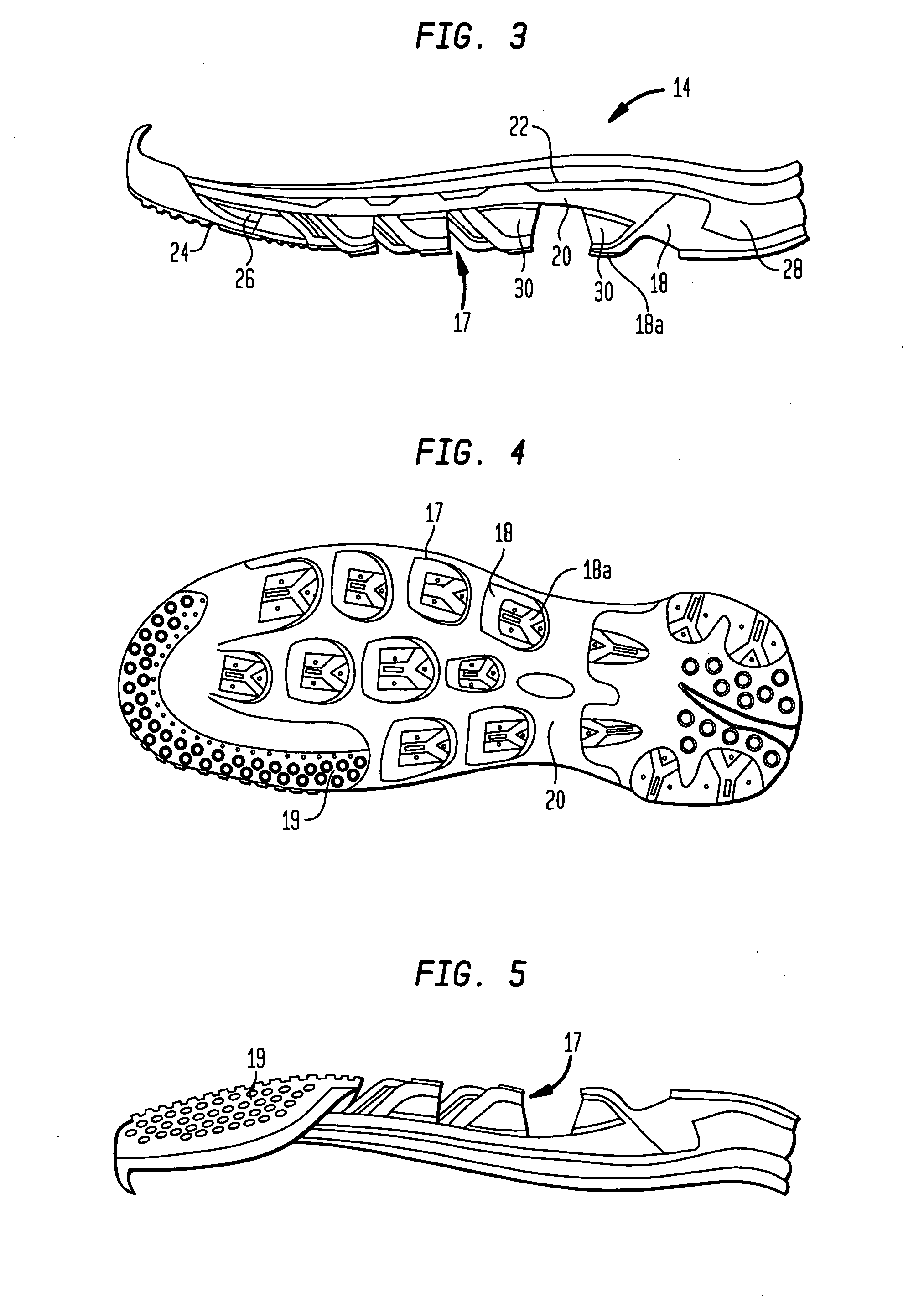
[0053] Referring now to the drawings, wherein like reference numerals represent like elements, there is shown in FIG. 1 an article of footwear according to an embodiment of the present invention. The particular article of footwear shown in FIG. 1 is in the form of an athletic shoe having an upper 12 and a sole 14. However, it is to be understood that the present invention could be implemented with any type of footwear, including sandals, boots, dress shoes, etc. Upper 12 is designed to receive the foot of a wearer by defining a portion of foot receiving cavity 13 therein. Upper 12 is structured to securely hold the wearer's foot and, to the extent possible, maintain the foot in contact with sole 14. Upper 12 is also preferably designed to provide support for the foot and to protect the foot from injury. Preferably, upper 12 covers the metatarsal and toe region of the foot as well as the instep portion and the heel portion of the foot.

[0054] While upper 12 may be of any configuratio...


PUM

PropertyMeasurementUnit
distancesaaaaaaaaaa
distancesaaaaaaaaaa
distancesaaaaaaaaaa

Abstract

An article of footwear having an upper and a sole is disclosed. The sole of the article of footwear includes a midsole having a support portion and a plurality of projections extending from the support portion. The sole of the article of footwear also includes a plate contacting the support portion having a body positioned in an area between the plurality of projections. The plate further includes a plurality of openings which correspond to the plurality of projections and allow the projections to extend below the body of the plate. The plate further includes a plurality of cantilever elements extending on at least one side and on the bottom of each of the plurality of projections. The projections and the corresponding cantilever elements interact with one another to form a plurality of lugs located on the sole of the article of footwear.

Description

CROSS-REFERENCE TO RELATED APPLICATION [0001] The present application claims the benefit of the filing date of U.S. Provisional Patent Application No. 60 / 781,126, filed Mar. 9, 2006, the entire disclosure of which is hereby incorporated by reference herein.BACKGROUND OF THE INVENTION [0002] The present invention relates generally to articles of footwear, and in particular to articles of footwear having an outsole having improved force distribution and stability on uneven surfaces or terrain. [0003] Most conventional footwear is designed to deflect ground forces by using hard, rigid bottoms. This causes the wearer to absorb much of the force and impact of any uneven terrain underfoot, leading to instability, bruising and risk of injury, including for example, the turning of an ankle. Typical shoe construction, particularly with respect to athletic shoe construction such as sneakers and hiking boots, includes an upper and a sole unit. The sole unit can include multiple layers of mater...

Claims


Application Information

Patent Timeline
Patent Type & Authority Applications(United States)
IPC IPC(8): A43B13/14A43B13/12A43C15/00A43B1/10
CPCA43B13/184A43B13/183A43B5/06A43B13/24
Inventor DILLON, PETERDARDINSKI, ALEXANDERVATTES, DAVID L.
Owner JABIL CIRCUIT INC
Why Eureka
Try Eureka