Compact scanning fiber device

a fiber device and compact technology, applied in the field of scanning fiber devices, can solve the problem that the housing may need to be longer than desired for certain implementations, and achieve the effect of reducing the length of the housing

Active Publication Date: 2009-09-01
UNIV OF WASHINGTON
View PDF156 Cites 129 Cited by
  • Summary
  • Abstract
  • Description
  • Claims
  • Application Information

AI Technical Summary

Problems solved by technology

Attaching the cantilevered free end portion to the end of the piezoelectric tube may have the potential drawback that the length of the housing may need to be longer than desired for certain implementations.

Method used


Image

  • Compact scanning fiber device
  • Compact scanning fiber device
  • Compact scanning fiber device

Examples


Embodiment Construction

[0016]In the following description, numerous specific details are set forth. However, it is understood that embodiments of the invention may be practiced without these specific details. In other instances, well-known circuits, structures and techniques have not been shown in detail in order not to obscure the understanding of this description.

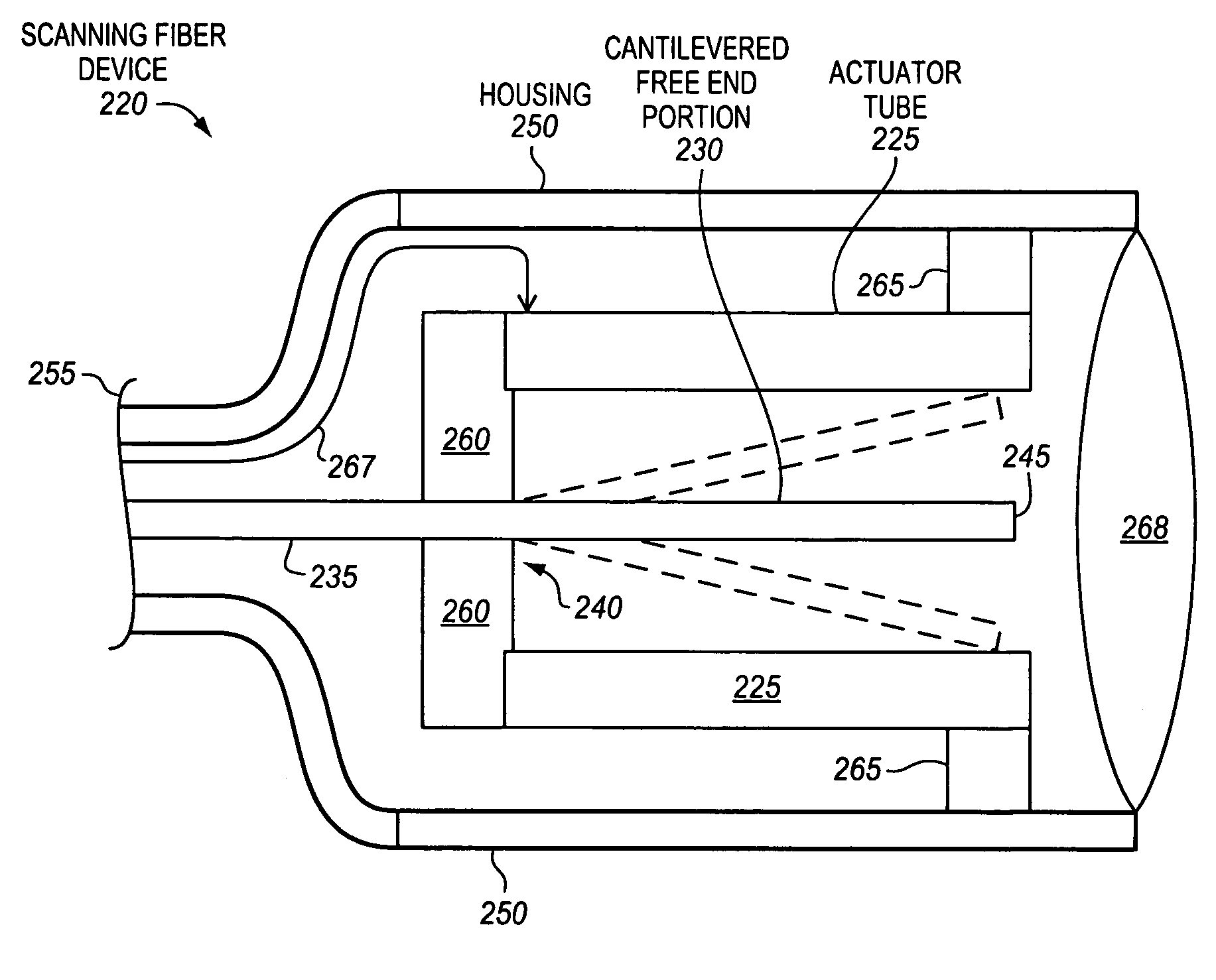
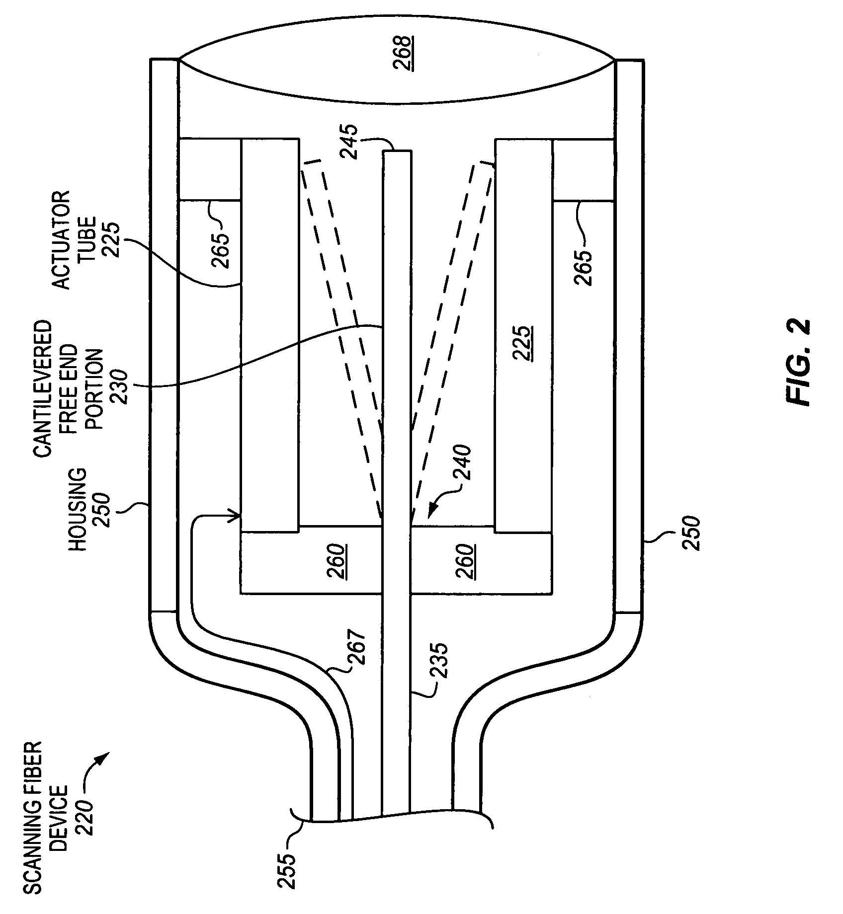
[0017]FIG. 2 is a cross-sectional side view of an example scanning fiber device 220, according to embodiments of the invention. The scanning fiber device includes an actuator tube 225, and a cantilevered free end portion 230 of an optical fiber 235. The cantilevered free end portion of the optical fiber has an attached end 240 that is coupled with the actuator tube, and a free end or tip 245 to be moved by the actuator tube. As shown, in embodiments of the invention, at least a portion of a length of the cantilevered free end portion of the optical fiber is disposed within the actuator tube, and may vibrate or move within the actuator tube. As ...


PUM


Abstract

Scanning fiber devices are disclosed. In one aspect, a scanning fiber device may include an actuator tube. The scanning fiber device may also include a cantilevered free end portion of an optical fiber. The cantilevered free end portion of the optical fiber may have an attached end that is coupled with the actuator tube. The cantilevered free end portion of the optical fiber may also have a free end to be moved by the actuator tube. At least a portion of a length of the cantilevered free end portion of the optical fiber may be disposed within the actuator tube. Methods of using scanning fiber devices are also disclosed.

Description

BACKGROUND[0001]1. Field[0002]Embodiments of the invention relate to scanning fiber devices. In particular, embodiments of the invention relate to scanning fiber devices having at least a portion of a cantilevered free end portion of an optical fiber disposed within an actuator tube, and to methods of making and using such scanning fiber devices.[0003]2. Background Information[0004]FIG. 1 is a cross-sectional side view of a known scanning fiber device 100. The scanning fiber device includes a housing 102. A piezoelectric tube 104 is included in the housing and attached to the housing with an attachment collar 106. A portion of an optical fiber 108 is inserted through the piezoelectric tube. A cantilevered free end portion 110 of the optical fiber is within the housing and attached to a distal end of the piezoelectric tube. The cantilevered free end portion is flexible and may be vibrated or moved. The piezoelectric tube has electrodes 112 thereon. Wires 114 are electrically coupled ...

Claims


Application Information

Patent Timeline
Patent Type & Authority Patents(United States)
IPC IPC(8): G02B6/26
CPCA61B1/0008A61B1/00165A61B1/00172A61B1/00183G02B26/103A61B5/0062G02B23/2476G02B23/26A61B1/04A61B5/0084
Inventor SEIBEL, ERIC J.SMITHWICK, QUINN Y. J.MYERS, JOHN A.JOHNSTON, RICHARD S.MELVILLE, CHARLES DAVID
Owner UNIV OF WASHINGTON
Why Eureka
Try Eureka