Optical fiber, and optical transmission line and optical transmission system using the same

a technology of optical fiber and optical transmission line, which is applied in the direction of optical fiber with desired dispersion, cladded optical fibre, instruments, etc., can solve the problems of signal distortion, transmission property deterioration, noise and non-linearity of optical fiber, etc., and achieve low transmission loss and high speed

Inactive Publication Date: 2008-03-04
LG CABLE LTD (KR)
View PDF6 Cites 1 Cited by
  • Summary
  • Abstract
  • Description
  • Claims
  • Application Information

AI Technical Summary

Benefits of technology

[0015]Also, it is another object of the present invention to provide an optical fiber in which a zero-dispersion wavelength, a dispersion, and an effective sectional area are optimized to enable a long-distance transmission (320 km repeaterless transmission) without signal distortion due to a low transmission loss in the system with a high speed (at least 10 Gb / s) and a mass storage (a channel spacing of 50 GHz or less).

Problems solved by technology

A power per channel is increased so as to enhance the transmission rate, but noises and non-linearity in optical fibers are increased and then a transmission property is deteriorated if the power per channel is increased as described above.
However, as the channel spacing becomes gradually narrowed, signal distortion is caused by a four-wave-mixing phenomenon, or a non-linear phenomenon such as cross phase modulation and XPM (Cross Phase Modulation).
Especially, if the low dispersion of the optical fiber is nearly close to the phase-matching condition, cross talk power is caused by a four wave mixing, finally causing a signal distortion.
If the power per channel is reduced to decrease intensity of the cross talk power, an optical signal noise ratio becomes worse, and therefore transmission distance gets short, resulting in an increased cost of the system upon long-distance transmission.
Also, intensity of the cross talk power is lowered as dispersion of the optical fiber increases, but its loss is increased since a length of the used optical fiber for dispersion compensation gets longer in proportion to the dispersion of the optical fiber.
However, the optical fiber proposed in the U.S. Pat. No. 5,327,516 may be used in the system enabling 360 km repeaterless transmission with a transmission rate of at least 5 Gb / s, a channel spacing of 1.0˜2.0 nm, and at least 4 channels, but it has a problem that the transmission property may be deteriorated due to the signal distortion by the four-wave mixing or the cross phase modulation as the non-linearity increases if it is used in the system having a transmission rate of at least 10 Gb / s, and a channel spacing of 1.0 nm or less.
However, the signal distortion by the four-wave mixing may appear in a pump wavelength range because the zero-dispersion wavelength is located in the S-band, for example near a pump wavelength for Raman amplification
In this case, it has a problem that the signal distortion by the four-wave mixing arises in a pump wavelength range because the zero-dispersion wavelength is located near 1,460 nm, for example near a pump wavelength for Raman amplification.

Method used


Image

  • Optical fiber, and optical transmission line and optical transmission system using the same
  • Optical fiber, and optical transmission line and optical transmission system using the same
  • Optical fiber, and optical transmission line and optical transmission system using the same

Examples


example 1

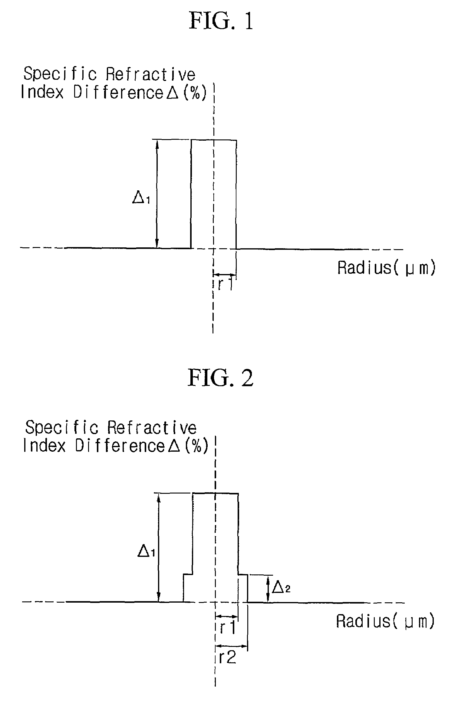
[0050](1) Radius: r1=3.64 μm

[0051](2) Specific refractive index difference: Δ1(%)=0.52%

[0052](3) Zero-dispersion wavelength: 1,315 nm

[0053](4) Dispersion

[0054]1,460 nm: 10.4 ps / nm-km, 1,530 nm: 14.5 ps / nm-km, 1,550 nm: 15.7 ps / nm-km, 1,625 nm: 19.6 ps / nm-km

[0055](5) Dispersion slope

[0056]1,550 nm: 0.055 ps / nm2-km

[0057](6) RDS

[0058]1,550 nm: 0.0035 nm−1

[0059](7) Effective sectional area

[0060]1,460 nm: 51 μm2, 1,530 nm: 54 μm2, 1,550 nm: 55 μm2, 1,625 nm: 59 μm2

example 2

[0061](1) Radius: r1=3.84 μm

[0062](2) Specific refractive index difference: Δ1(%)=0.46%

[0063](3) Zero-dispersion wavelength: 1,312 nm

[0064](4) Dispersion

[0065]1,460 nm: 10.8 ps / nm-km, 1,530 nm: 15.1 ps / nm-km, 1,550 nm: 16.2 ps / nm-km, 1,625 nm: 20.2 ps / nm-km

[0066](5) Dispersion slope

[0067]1,550 nm: 0.056 ps / nm2-km

[0068](6) RDS

[0069]1,550 nm: 0.0035 nm−1

[0070](7) Effective sectional area

[0071]1,460 nm: 57 μm2, 1,530 nm: 61 μm2, 1,550 nm: 62 μm2, 1,625 nm: 66 μm2

example 3

[0072](1) Radius: r1=3.57 μm, and r2=4.53 μm

[0073](2) Specific refractive index difference: Δ1(%)=0.53%, and Δ2=0.097%

[0074](3) Zero-dispersion wavelength: 1,313 nm

[0075](4) Dispersion

[0076]1,460 nm: 10.7 ps / nm-km, 1,530 nm: 15.0 ps / nm-km, 1,550 nm: 16.2 ps / nm-km, 1,625 nm: 20.1 ps / nm-km

[0077](5) Dispersion slope

[0078]1,550 nm: 0.057 ps / nm2-km

[0079](6) RDS

[0080]1,550 nm: 0.0035 nm−1

[0081](7) Effective sectional area

[0082]1,460 nm: 52 μm2, 1,530 nm: 55 μm2, 1,550 nm: 56 μm2, 1,625 nm: 60 μm2


PUM


Abstract

Disclosed is an optical fiber suitable for an optical transmission line used in WDM system, particularly a single-mode optical fiber whose zero-dispersion wavelength is positioned in a short wavelength band (less than 1,370 mm) so as to enable high-speed mass-storage signal transmission over S-C-L bands (1,460˜1,625 nm) and whose dispersion value and effective sectional area are optimized. In the optical fiber, a dispersion value is at least 9 ps / nm-km at 1,460 nm, an effective sectional area is 45-65 μm2 at 1,460 rim, a zero-dispersion wavelength exists at 1,370 nm or less, and a dispersion slope is positive. In addition, RDS (Relative Dispersion Slope) is 0.0032˜0.0038 nm−1 at 1,550 nm. Thus, the optical fiber enables to repress non-linearity and signal distortion to the maximum during 320 km repeaterless transmission with a transmission rate of 10 Gb / s or more over S-C-L bands, a channel spacing of 50 GHz or less, 16 channels, and a signal power of 0 dBm / ch or 2 dBm / ch.

Description

TECHNICAL FIELD[0001]The present invention relates to an optical fiber suitable for an optical transmission line used in wavelength division multiplexing (WDM) transmission system, particularly to a single-mode optical fiber whose zero-dispersion wavelength is positioned in a short wavelength band (less than 1,370 mm) so as to enable high-speed mass-storage signal transmission over S-C-L bands (1,460 to 1,625 nm) and whose dispersion value and effective sectional area are optimized.BACKGROUND ART[0002]In the case of a wavelength division multiplexing (WDM) transmission system, transmission capacity may be effectively enhanced by increasing a transmission rate, reducing a channel spacing or widening a transmission wavelength range.[0003]Recently, the transmission rate of the system has increased from 2.5 Gb / s to 10 Gb / s, and the transmission system having 40 Gb / s will be generally used in the near future. A power per channel is increased so as to enhance the transmission rate, but no...

Claims


Application Information

Patent Timeline
Patent Type & Authority Patents(United States)
IPC IPC(8): G02B6/02
CPCG02B6/02014G02B6/02242G02B6/02266G02B6/0228G02B6/03633
Inventor PARK, HYE-YOUNGMUN, JUN-HO
Owner LG CABLE LTD (KR)
Why Eureka
Try Eureka