Restraint device

a technology of resisting device and reel device, which is applied in the field of resisting device, can solve the problems of not being suitable for use as handcuffs, the de michieli device is not intended to be useful for constraining a resisting subject, and the ratcheting mechanical reel device could become a dangerous weapon, etc., and achieve the effect of not increasing the distance between the bracelets

Active Publication Date: 2008-03-11
KIM KEUN J +1
View PDF32 Cites 24 Cited by
  • Summary
  • Abstract
  • Description
  • Claims
  • Application Information

AI Technical Summary

Benefits of technology

[0016]The bracelets of the handcuffs or shackles may be applied to the subject while the subject's hands or feet are far apart and will retract automatically to a predetermined distance. Thus, the arresting officer does not need to have the hands of the subject together in order to apply the restraint devices. In the present invention the restraint devices maintain the bracelets locked while the bracelets are retracting, thus providing a continual limiting of movement of the subject while the subject is securely locked.
[0017]This invention is designed to help the arresting officer. When the subject resists arrest, this restraining device gives the officer the freedom of not having to force the subject's hands together to put the restraining device onto the subject. The restraint device is not fixed in length. Rather, it may become any length which is required and it may retract to a predetermined size. The first advantage of this restraint device over the prior art is that it may become any length by merely opening the device's bracelet on the central holder without a key.
[0018]The second advantage is that a retracting device retracts one of the bracelets automatically to the original position once the restraint device is on the subject.
[0019]The third advantage is that the distance between the bracelets may not increase, but may only decrease.
[0020]The fourth advantage is that when one bracelet is on the subject, the arresting officer can stay away from a dangerous subject and lock the other bracelet to any anchored place to restrain the subject. This is made possible by an automatic retraction / extension length-control feature of the restraint devices.

Problems solved by technology

This is a better device than the fixed-length handcuffs, but when the subject resists, the ratcheting mechanical reel device could become a dangerous weapon as the subject could swing it at the arresting officers.
The De Michieli device would not be suitable for use as handcuffs.
The system of the De Michieli patent is not intended to be useful for constraining a resisting subject.

Method used


Image

  • Restraint device
  • Restraint device
  • Restraint device

Examples


first embodiment

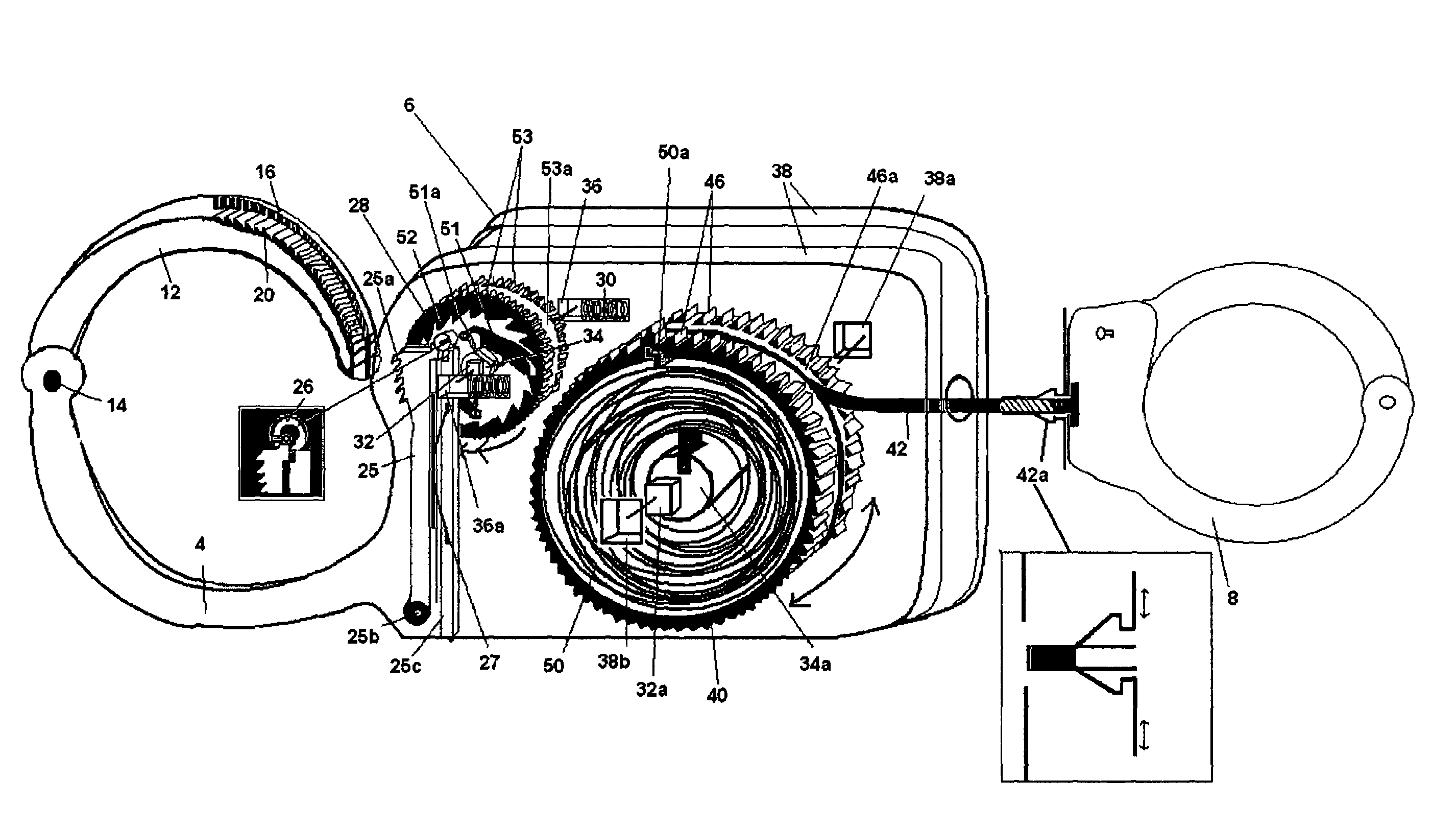
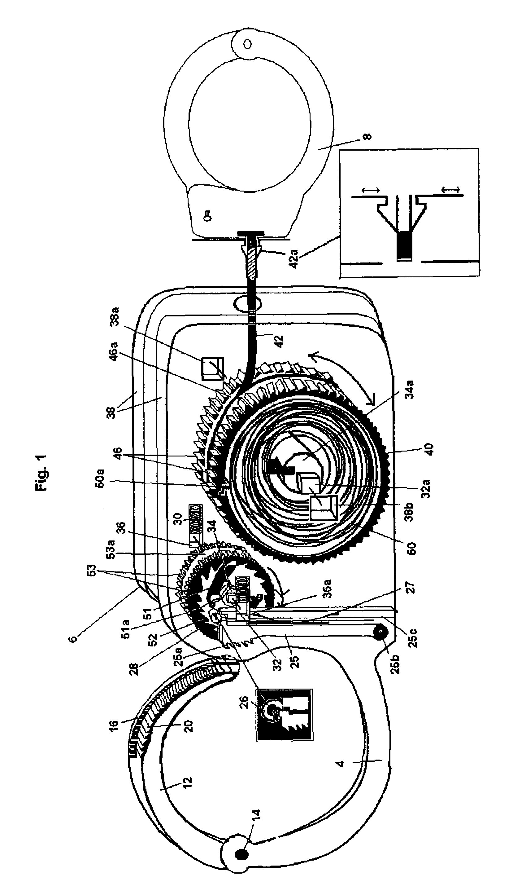
[0033]this invention will be described with reference to FIG. 1.

[0034]The restraining system 2 is made up of a first bracelet 4 having a press mechanism 16 on the left; a central holder 6 having a one-way locking mechanism 28, a retraction / extension mechanism 40, and a line 42 attached to the retraction / extension mechanism 40; and a second bracelet 8 on the right.

[0035]The restraining system 2 is preferably made up of a first bracelet 4 with central holder 6 and a second bracelet 8. The central holder 6 has a one-way locking mechanism 28 and a retraction / extension mechanism 40. The one-way locking mechanism 28 and the retraction / extension mechanism 40 are engaged and disengaged by a press mechanism 16 which is part of the first bracelet 4.

[0036]The upper section 12 of the first bracelet 4 has a press mechanism 16 and a set of ratchets 20. FIG. 1 shows the ratchets 20 of the upper section 12 of the bracelet 4 disengaged from the pawls 25a of the locking / unlocking mechanism 25. When t...

second embodiment

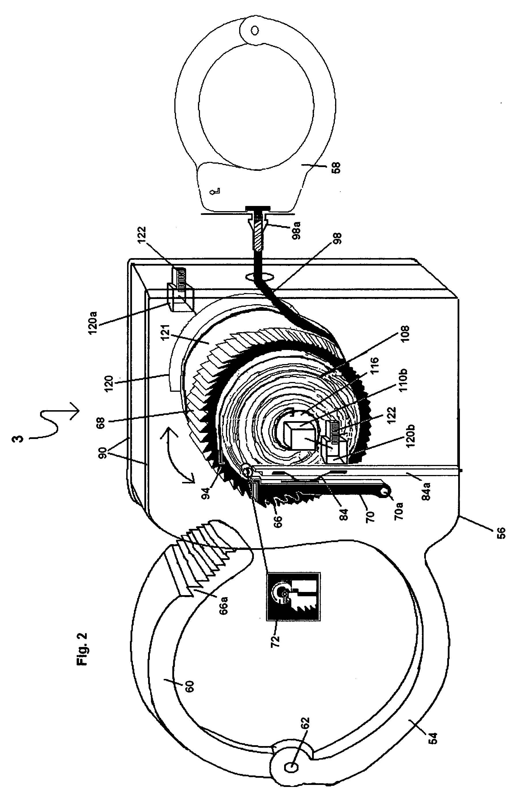
[0045]The restraint devices 3 of the second embodiment will be described with reference to FIGS. 2 and 3.

[0046]The restraint devices 3 of the second embodiment have the same working principle as those of the first embodiment and are made up of a first bracelet 54 with the central holder 56 and a second bracelet 58 on the right side of the central holder 56. The restraint devices 3 of the second embodiment do not use the one-way locking mechanism 28 (FIG. 1) of the first embodiment.

[0047]FIG. 2 shows the upper section 60 of the bracelet 54 having ratchets 66a which is attach by pivot pin 62. The upper section 60 of the bracelet 54 is brought down so that the ratchets 66a engage with the pawls 66 of the locking / unlocking mechanism 70. The locking / unlocking mechanism 70 is pivoted about a pivot member 70a which is attached to the cover plate 90. A spring 84 push the locking / unlocking mechanism 70 toward the left, which is the locked position.

[0048]When the ratchets 66a of the upper sec...


PUM


Abstract

Restraint devices which have a first bracelet, a second bracelet, and a central holder. In one embodiment, the central holder contains a one-way locking mechanism and a retraction / extension mechanism. In a second embodiment, the central holder comprises a retraction / extension mechanism. One end of a line is attached to the second bracelet and the other end of the line is attached to the retraction / extension mechanism, which urges the second bracelet toward the central holder. When the first bracelet is open, the line may be extended from the central holder or retracted to the central holder. When the first bracelet is closed, the retraction / extension mechanism is engaged, causing the one way locking mechanism / one way clutch to allow retraction of the bracelet toward the central holder, but to prevent extension of the bracelet away from the central holder. A line stopper is disclosed which connects with the line between the retraction / extension mechanism and the second bracelet.

Description

CROSS-REFERENCE TO RELATED APPLICATIONS[0001]This application is a continuation-in-part of application Ser. No. 11 / 143,284, filed Jun. 3, 2005 now abandoned.STATEMENT REGARDING FEDERALLY SPONSORED RESEARCH OR DEVELOPMENT[0002](Not applicable)REFERENCE TO SEQUENTIAL LISTING, A TABLE, OR A COMPUTER PROGRAM LISTING APPENDIX SUBMITTED ON A COMPACT DISC[0003](Not applicable)BACKGROUND OF THE INVENTION[0004]1) Field of the Invention[0005]This invention relates to restraining systems. More particularly, this invention relates to restraining systems such as handcuffs or shackles which may be applied to a subject while the hands or feet are far apart and, once locked, the distance between the bracelets of the restraining systems may decrease, but cannot increase.[0006]2) Description of the Related Art[0007]It is known to use a restraining system to hold a subject's hands together. When using the restraining systems disclosed in the prior art, three or four arresting officers must use overpow...

Claims


Application Information

Patent Timeline
Patent Type & Authority Patents(United States)
IPC IPC(8): E05B75/00
CPCE05B75/00Y10T70/402Y10T70/404
Inventor KIM, KEUN J.KIM, KAY K.
Owner KIM KEUN J
Why Eureka
Try Eureka