Assembling-disassembling machine provided with a overturnable mounting-dismounting tool

a technology of mounting and dismounting tool, which is applied in the direction of transportation and packaging, tyre repairing, tyre parts, etc., can solve the problems of substantial unbalance in the machine, unavailability of the available area without cost increase, and unduly increase production costs, so as to achieve rapid and effective change and low effort

Active Publication Date: 2008-03-11
BUTLER ENG & MARKETING
View PDF18 Cites 22 Cited by
  • Summary
  • Abstract
  • Description
  • Claims
  • Application Information

AI Technical Summary

Benefits of technology

[0007]Another object of the present invention is to provide an assembling-disassembling machine provided with a tool which can be moved away from and towards the rotatable support group with a minimal effort and without causing unbalance in the machine trim.
[0008]Another object of the present invention is to provide an assembling-disassembling machine which can rapidly and effectively change from a configuration in which its mounting-dismounting tool is located in a working position to a configuration with mounting / dismounting tool in a rest position with low efforts by the operator with respect to those required when dealing with conventional assembling-disassembling machines.

Problems solved by technology

Accidents may occur when the upright is subjected to an angular movement, and thus a specific lateral protection is required about the upright which would unduly increase the production costs.
In most cases such an area is not ready available without cost increase.
Furthermore, according to such a solution in order to move the working tool between its working and rest positions a relatively large weight has to be displaced each time which might result in substantial unbalance in the machine.
Another drawback of such a tool system that provides for displacing the tool away from its working position is that the working area available for the operator (tyreman) to carry out other tyre disassembling from or mounting onto a wheel rim located on the self-centring group is limited even after upright has been (partly) overturned rearwards.
Such a circumstance can be a penalizing factor for the operator's movements around and above the rotatable support group and accidents may occur owing to the presence of the tool hanging near the supporting group.

Method used


Image

  • Assembling-disassembling machine provided with a overturnable mounting-dismounting tool
  • Assembling-disassembling machine provided with a overturnable mounting-dismounting tool
  • Assembling-disassembling machine provided with a overturnable mounting-dismounting tool

Examples


Embodiment Construction

[0017]In the accompanying drawings, the same or similar parts or components have been indicated with the same reference numerals.

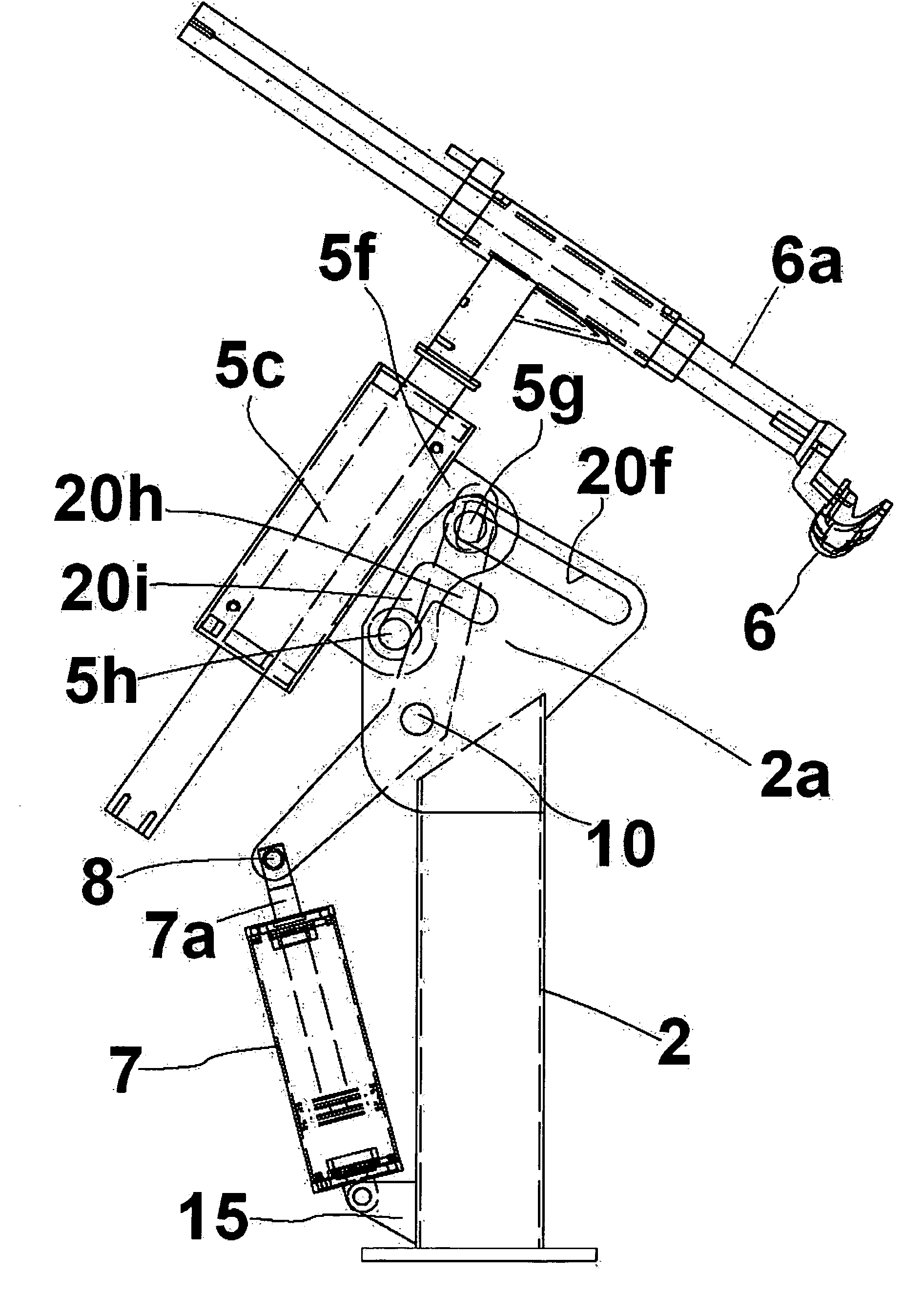
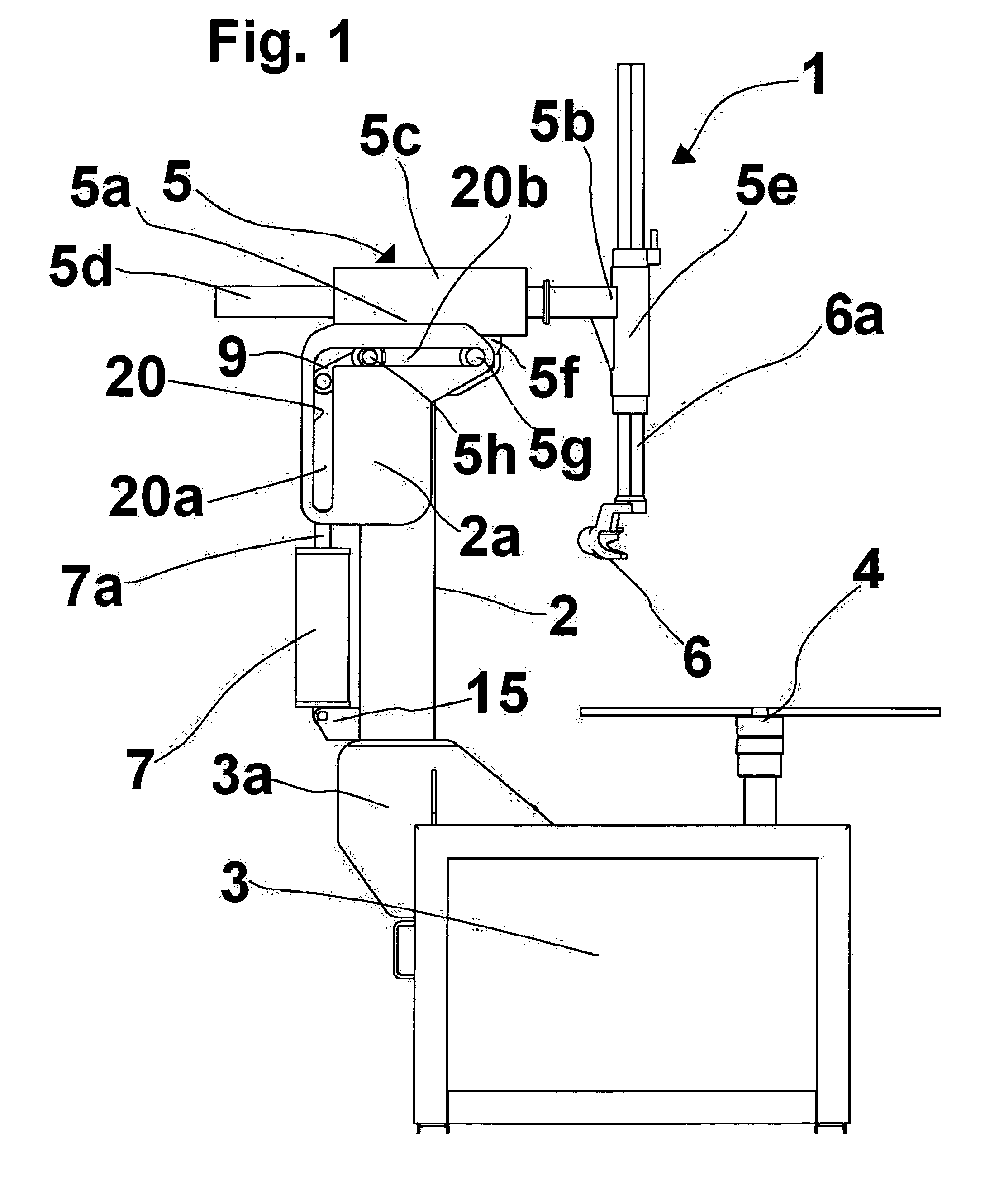
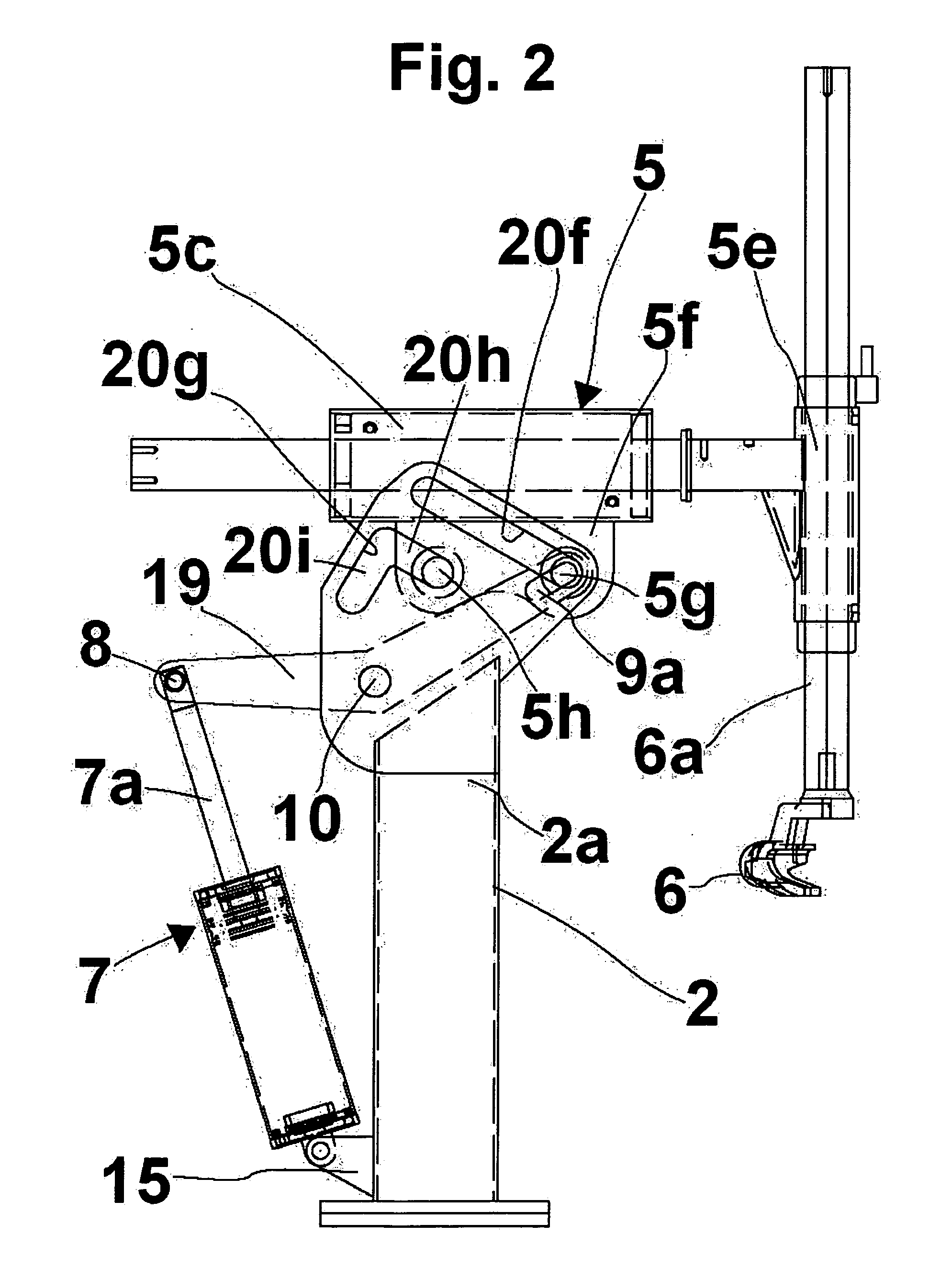
[0018]With reference first to FIG. 1, there is illustrated an assembling-disassembling machine, generally designed with the reference numeral 1, comprising a vertical column or upright 2, supported by a base 3 from which a rotatable support device (table) 4 extends upwards and is designed to lock and set in rotation a motor vehicle wheel rim (not shown) about the axis of rotation of the wheel. More particularly, the column 2 can be advantageously supported by a rear lug 3a of the base 3.

[0019]One end 5a of a tool-carrying arm 5 is secured at the top of the column 2, and extends transversely thereto. The tool-carrying arm 5 at its other end 5b supports a sleeve 5e in which a tang 6a of a mounting-dismounting tool 6 can slide and be locked in position in any suitable way.

[0020]Constructively, the vertical column 2 can support at the top thereof one or prefer...


PUM


Abstract

The present invention relates to an assembling-disassembling machine provided with a base, a rotating support device (4) for a wheel rim or tyred wheel, an upright or column element (2) extending upwards from the base, and at least one mounting / dismounting tool (6) supported by the upright or column element (2) and mounted on one end of a tool carrying arm (5) in order to transversely extend from the upright element (2). The assembling-disassembling machine also comprises rotating and shifting support means located between the upright or column element (2) and the tool-carrying arm (5) at an upper level with respect to the rotating support device (4), whereby said tool-carrying arm (5) can be rotated and shifted with respect to the upright or column element (2) between a working position, in which the tool (6) is close to the rotating support device (4) and at least one rest position far from the rotating support device (4).

Description

FIELD OF INVENTION[0001]The present invention relates to an assembling-disassembling machine provided with a mounting-dismounting tool which can be displaced between a working position, in which it can be used to mount-dismount a tyre onto and from a wheel rim located on the assembling-disassembling machine, and a rest position which is far from the working position, whereby when the tool is in the rest position it is not an obstacle for other tyred-wheel maintenance operations. Assembling-disassembling machines comprising a base, a rotatable self-centring support group designed to support and hold in position a wheel rim, which is located on the support base, an upright extending generally upwards from the rear side of the support base, one or more working tools extending from the upright, have been proposed so far. To dismount a tyred wheel, the tyred wheel is located and blocked in position onto the rotatable self-centring support group, then a bead releasing step is carried out ...

Claims


Application Information

Patent Timeline
Patent Type & Authority Patents(United States)
IPC IPC(8): B60C25/132B60C25/01
CPCB60C25/138
Inventor GONZAGA, TULLIO
Owner BUTLER ENG & MARKETING
Why Eureka
Try Eureka