Pneumatic nail gun

a nail gun and pneumatic technology, applied in the field of pneumatic nail guns, can solve the problems of high manufacturing cost of nail guns, complicated air flow passage distribution, and increased cost of gun bodies, so as to improve the operating facility of nail guns, prevent the complexity of conventional guns, and reduce the cost of nail guns

Inactive Publication Date: 2008-03-11
DE POAN PNEUMATIC
View PDF12 Cites 11 Cited by
  • Summary
  • Abstract
  • Description
  • Claims
  • Application Information

AI Technical Summary

Benefits of technology

[0008]The pneumatic nail gun provides the main passage and the valve bolt to prevent the complexities of conventional air flow passage distribution and valve controlling mechanism. The main passage is simplified to improve the operating facility of the nail gun and lower the cost thereof.
[0009]Furthermore, the valve bolt has a small size and a simple structure, which may be made of light material. Then the valve bolt is relatively sensitive to be driven by the high pressure air. Moreover, compressed high pressure air gathered in the top air flow passage drives the valve bolt to close the valve, if the head of the nail gun falls down to the ground, the valve bolt is prev

Problems solved by technology

As such, the nail gun has a high manufacturing cost and complicated air flow passage distribution.
However, the valve control device has complicate assembly and more passages in the n

Method used


Image

  • Pneumatic nail gun
  • Pneumatic nail gun
  • Pneumatic nail gun

Examples


Embodiment Construction

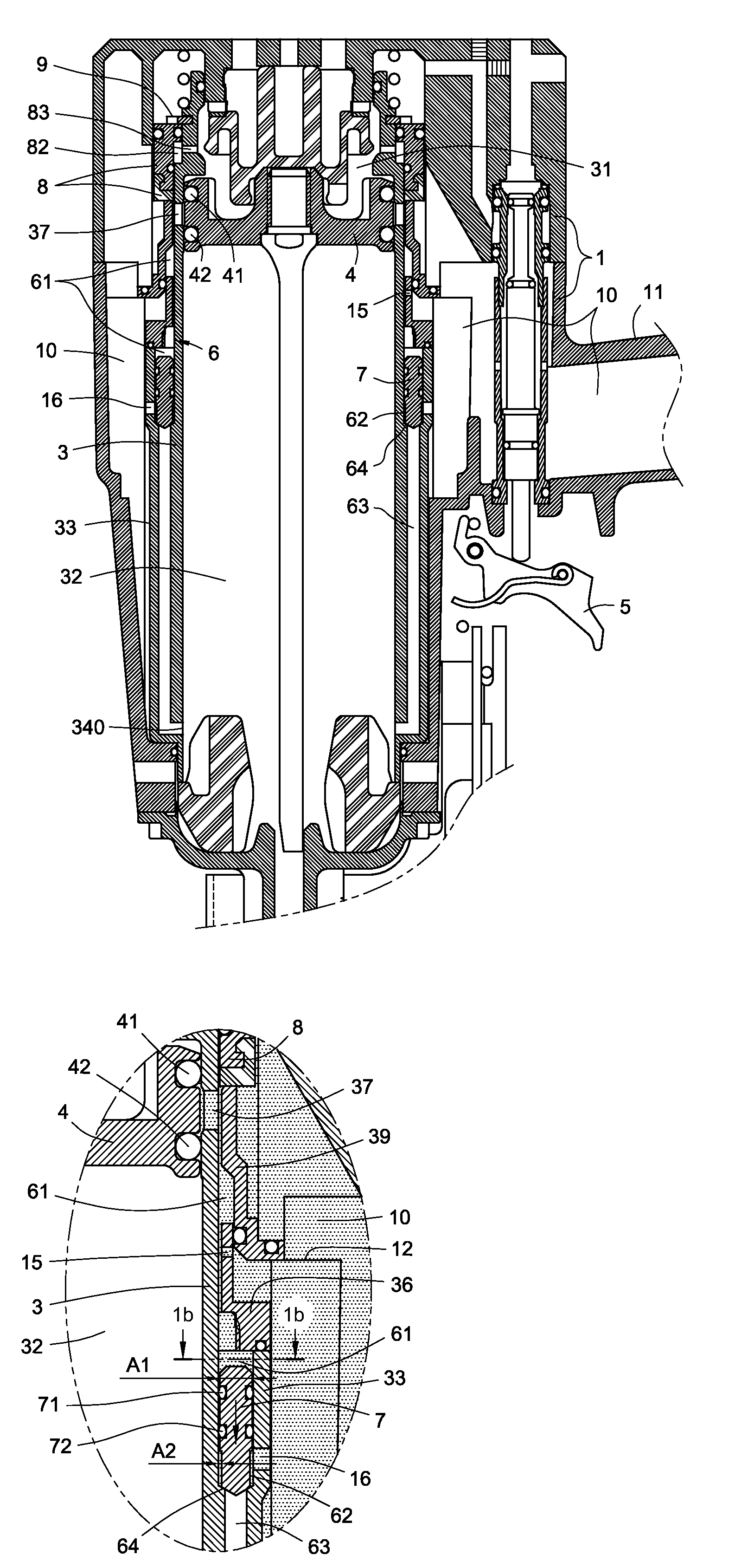
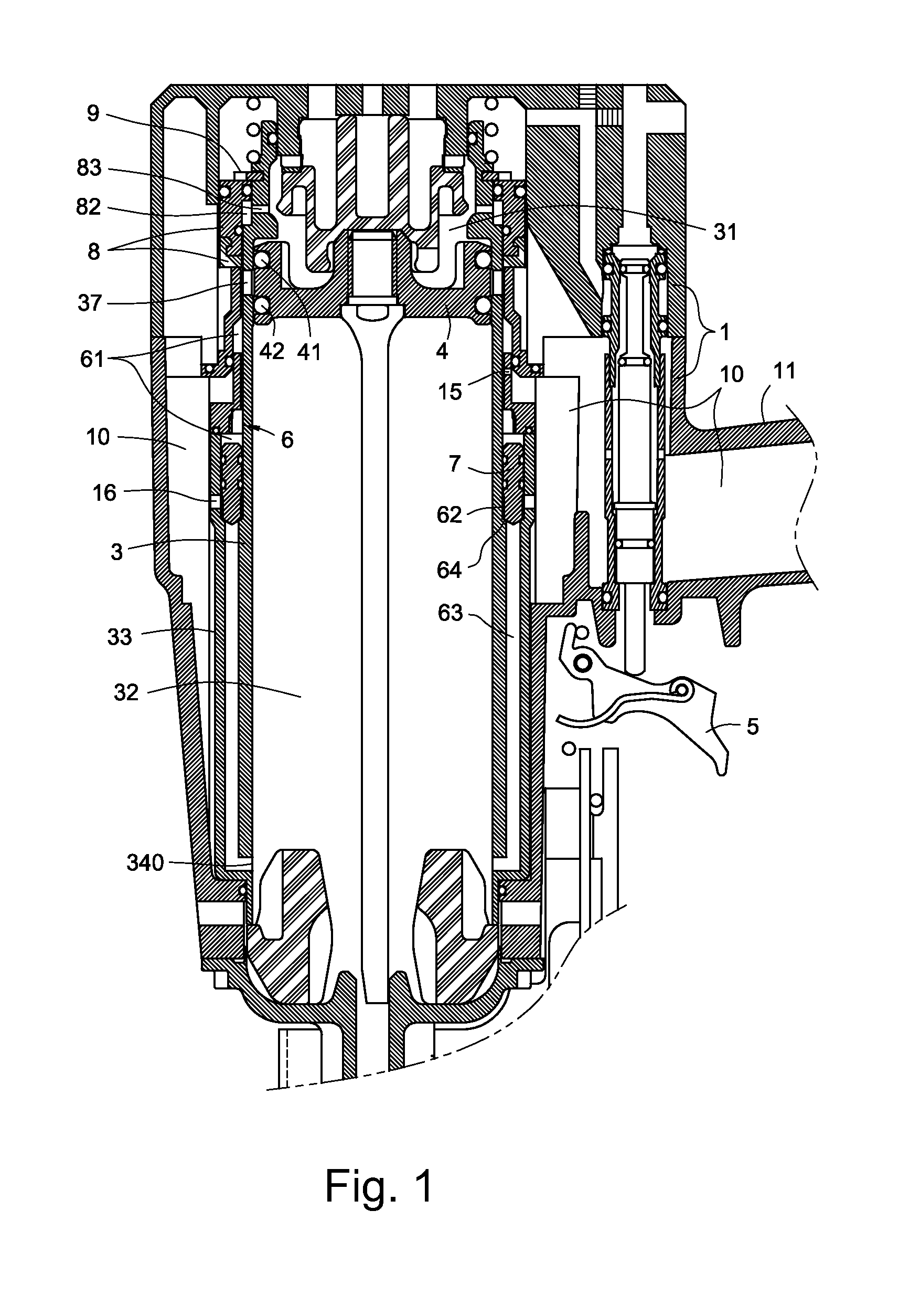
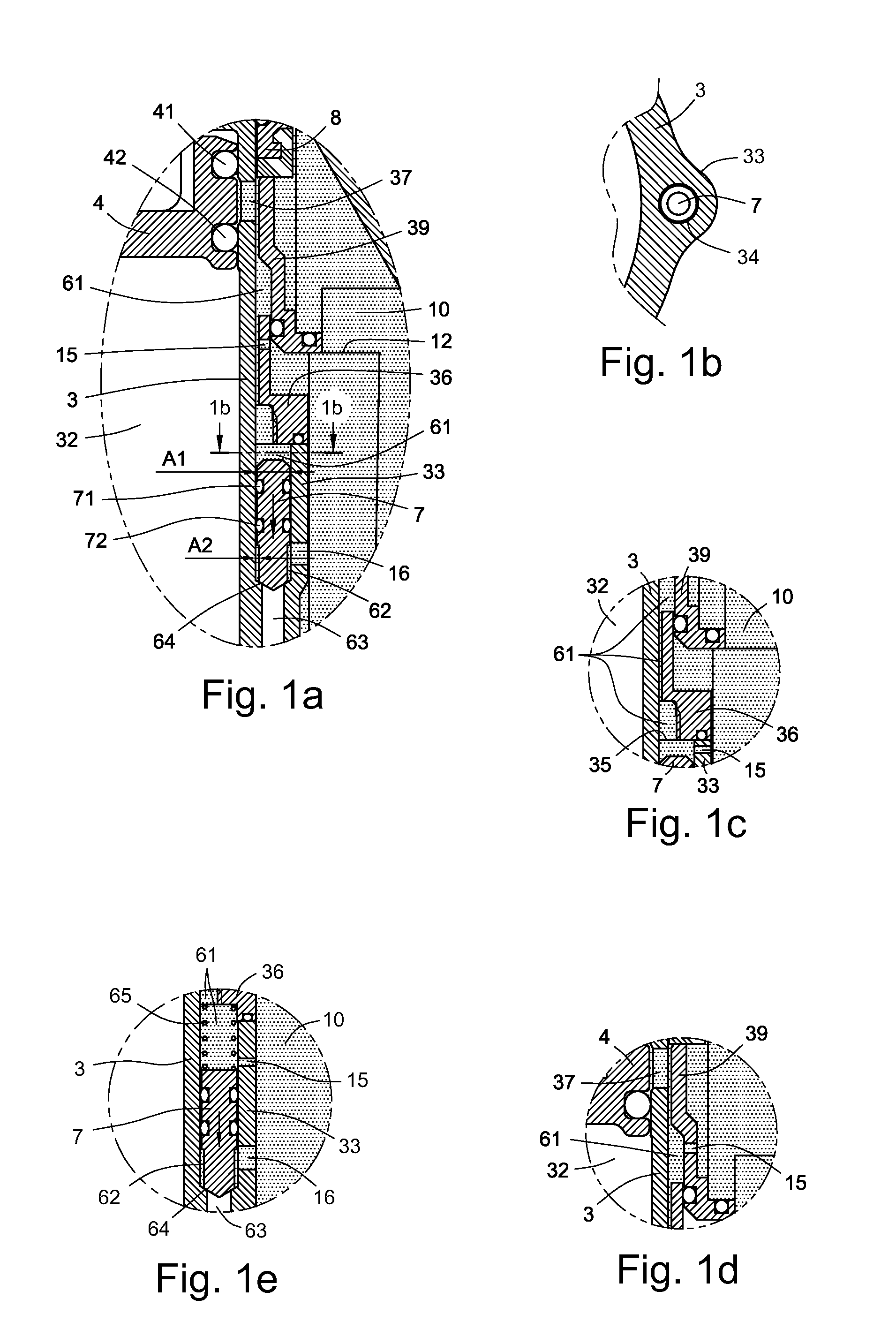
[0022]Referring to FIG. 1, a pneumatic nail gun according to a first embodiment of the present invention is shown. The pneumatic nail gun has a gun body 1, a movable cylinder 3 installed in the gun body 1, a head valve 8 integrally formed or disposed on top of the movable cylinder 3, a hitting piston 4 disposed in the movable cylinder 3, a main air housing 10 formed in the nail gun, and at least one main air flow passage 6.

[0023]The hitting piston 4 includes at least two air tight rings 41 and 42, which can divide the cylinder 3 into a top cylinder chamber 31 and a bottom cylinder chamber 32 when the hitting piston 4 move downward to hit nails or move upward to reposit.

[0024]The main air housing 10 is disposed between a handle 11 of the nail gun and the peripheral portion of the cylinder 3 for continuously gathering high pressure air from air supply via a free end of the handle 11 to maintain a constant air pressure therein (see dots area in FIG. 5). A trigger 5 is disposed at one e...


PUM

PropertyMeasurementUnit
Pressureaaaaaaaaaa
Areaaaaaaaaaaa

Abstract

A pneumatic nail gun includes a gun body having a movable cylinder therein; a hitting piston disposed in the cylinder; a main air housing collecting a compressed high pressure air with a constant pressure; and at least one main passage disposed at a peripheral portion of the cylinder or a side of the main air housing, the at least one main passage having a valve bolt therein to divide the main passage into a top passage, a middle valve chamber, and a bottom passage, the top passage and the middle valve chamber being connecting with the main air housing for introducing and gathering high pressure air therein, the middle valve chamber being connecting with the bottom passage via the main valve opening, the valve bolt being capable of controlling the opening and closing of the main valve opening for rapidly repositing the piston.

Description

BACKGROUND[0001]The present invention relates to pneumatic nail guns, and particularly to a pneumatic nail gun having a movable cylinder for a hitting piston of the nail gun driven by the high pressure air to upwardly move for reposition and a head valve disposed on top of the movable cylinder.[0002]A typical pneumatic nail gun has a gun body, a main air housing formed in the gun body to continuously collect the compressed high pressure air for nail hitting, a movable or fixed cylinder disposed in the gun body, and a hitting piston installed inside the cylinder and divided the cylinder into a top and a bottom cylinder chambers. Moreover, a trigger disposed on the gun body may be pressed to have the high pressure air guided into the top cylinder chamber to drive the piston downwardly move for hitting the nails, and be released to have the high pressure air discharged from the top cylinder chamber and guided into the bottom cylinder chamber to upwardly move the piston for reposition.[...

Claims


Application Information

Patent Timeline
IPC IPC(8): B25C1/04
CPCB25C1/041
Inventor WEN, WAN-FU
Owner DE POAN PNEUMATIC
Why Eureka
Try Eureka