Pneumatic Nail Gun

Inactive Publication Date: 2008-05-08
DE POAN PNEUMATIC
View PDF12 Cites 5 Cited by
  • Summary
  • Abstract
  • Description
  • Claims
  • Application Information

AI Technical Summary

Benefits of technology

[0006]A pneumatic nail gun of the present invention can overcome the problems of lacking of pushing force of the pressure air for reposition of hitting piston, which can also save the space inside the nail gun to distribute mechanism as well as has a simple air flow passage distribution so as to ensure the nail gun having a lower cost and a high facility for operation.
[0008]The pneumatic nail gun provides the main passage to substitute of the return passage for continuously guiding the compressed air to drive the hitting piston to upwardly move to reposit. Moreover, this pneumatic nail gun employs the main passage and a valve bolt to substitute the conventional valve mechanisms and the passages, in which, the main passage and the bottom valve are both disposed at a peripheral portion of the nail gun for simplifying the distribution of the nail gun, so as to improve the operating facility of the nail gun and lower the cost thereof.
[0009]Furthermore, the valve bolt has a small size and a simple structure, which may be made of light material. Then the valve bolt is relatively sensitive to be driven by the high pressure air. Moreover, compressed high pressure air gathered in the top air flow passage drives the valve bolt to close the valve, if the head of the nail gun falls down to the ground, the valve bolt is prevented from shaking or vibrating. The valve bolt has a high position controlling capability.

Problems solved by technology

However, the return passage can only collect compressed air during the hitting piston downwardly moving to hitting nails, which can not continuously guide compressed air thereinto and maintain a high pressure therein.
Therefore, the pushing force generated by the limited compressed air in the return passage may not ensure the hitting piston having a stable reposition process.
During the process of continuously hitting nails, slower and unstable reposition of the hitting piston may impact the speed and efficiency of hitting nails.
However, the valve mechanisms are disposed in the gun body far away from the cylinder, it request that the gun body has a larger space and complicated passages to realize introducing the high pressure air into the bottom chamber to drive the hitting piston upwardly move to reposit.
Therefore, the nail gun has a high manufacturing cost and complicated air flow passages.

Method used


Image

  • Pneumatic Nail Gun
  • Pneumatic Nail Gun
  • Pneumatic Nail Gun

Examples


first embodiment

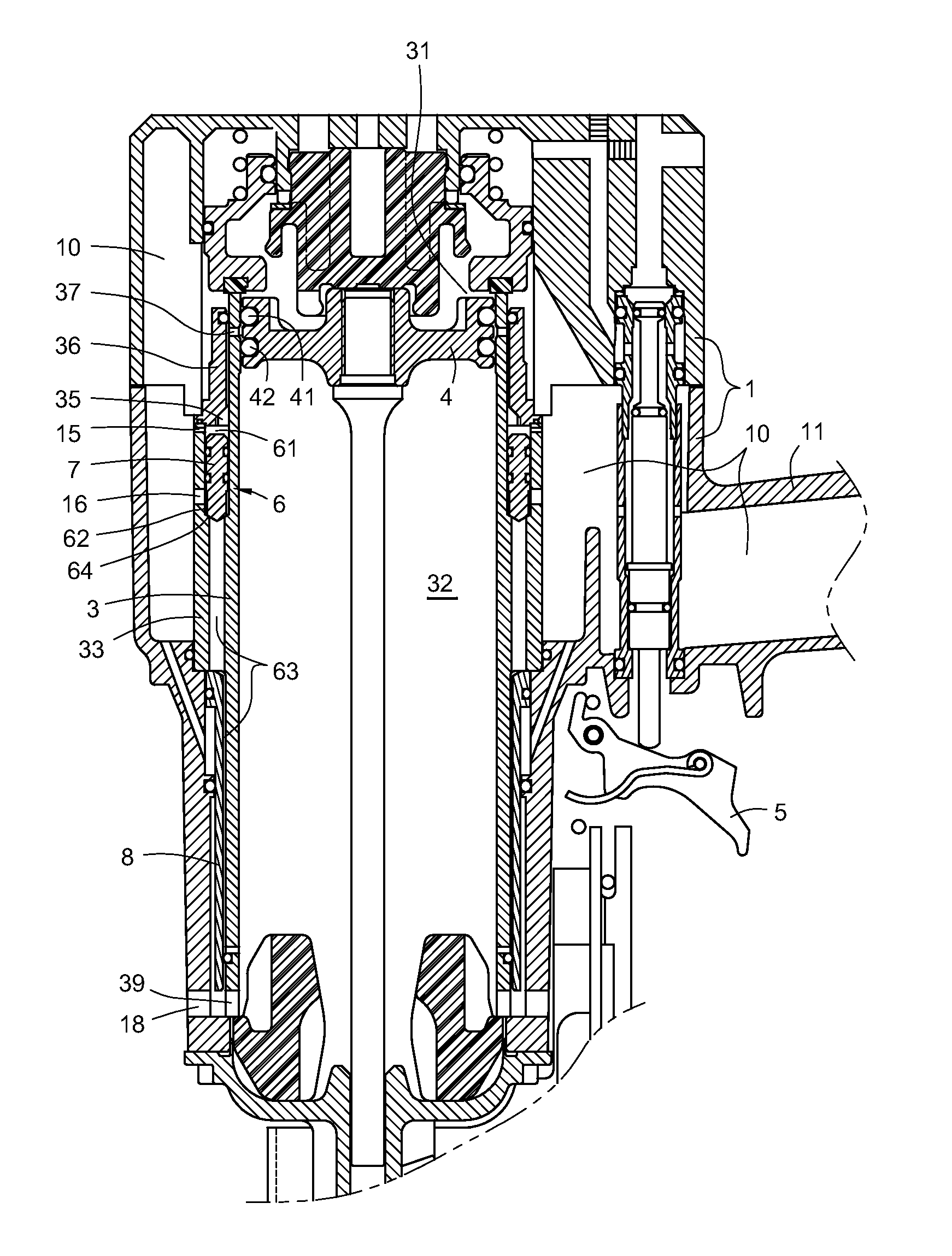
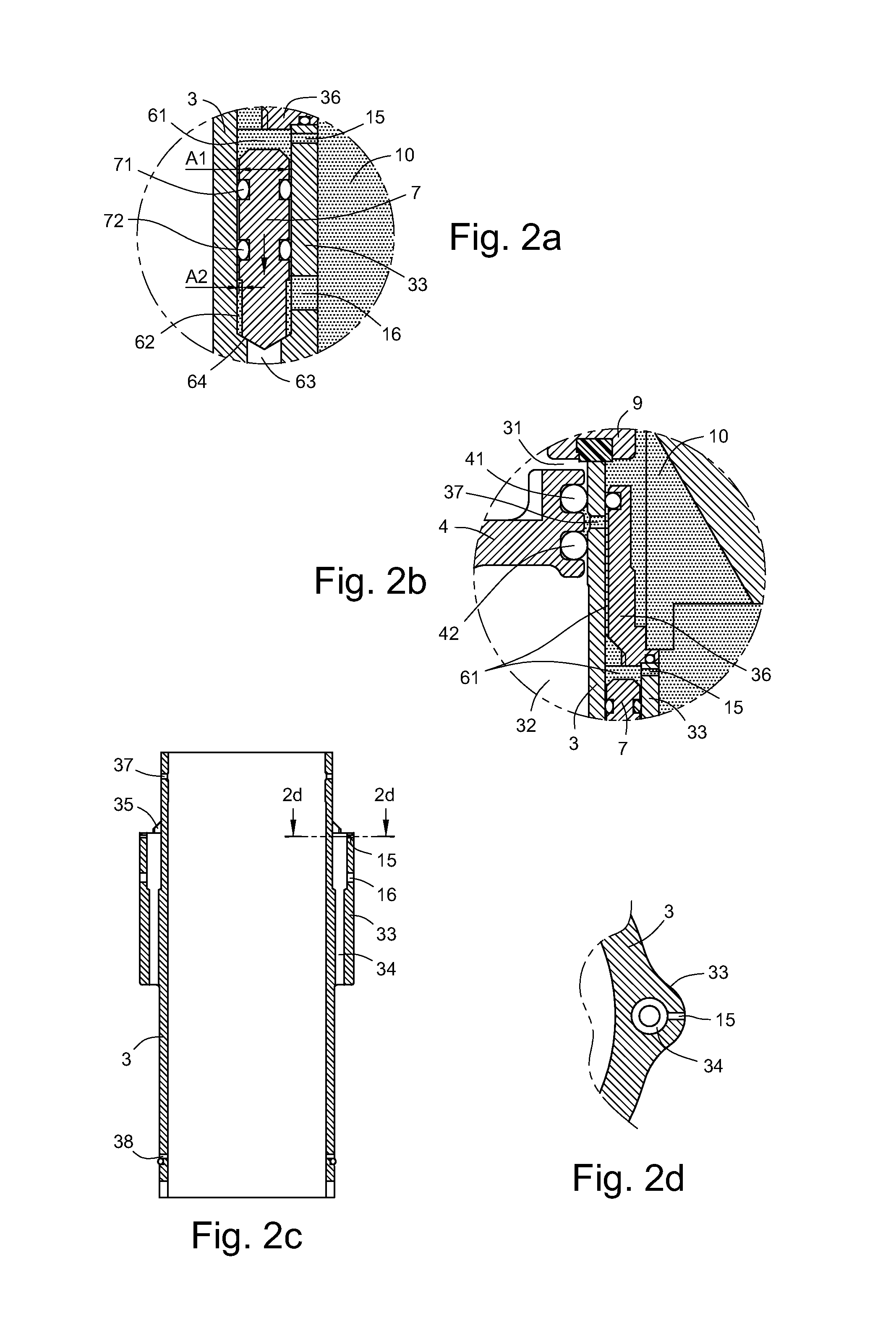
[0021]Referring to FIG. 1, a pneumatic nail gun according to the present invention is shown. The pneumatic nail gun has a gun body 1, an immovable cylinder 3, a hitting piston 4 disposed in the immovable cylinder 3, a main air housing 10 disposed in the nail gun, and at least one main air flow passage 6.

[0022]The hitting piston 4 includes at least two air tight rings 41 and 42, which can divide the cylinder 3 into a top chamber 31 and a bottom chamber 32 when the hitting piston 4 move downward to hit nails or move upward to reposit (shown in FIG. 6).

[0023]The main air housing 10 is disposed between a handle 11 of the nail gun and the peripheral portion of the cylinder 3 for gathering continuously introducing high pressure air from atmosphere via a free end of the handle 11 (shown in FIGS. 2 and 5). The main air housing 10 further includes a trigger 5 disposed at one end of the main air housing 10 for driving the hitting piston 4 downwardly move to hit nails and upwardly reposit.

[002...

fourth embodiment

[0035]Referring to FIG. 9, a side, cross-sectional view of a part of a pneumatical nail gun according to the present invention is shown. The gun body includes a rib wall 13 disposed adjacent to the cylinder 30, the rib wall 13 includes at least one rib hole 14, the top portion of the rib wall 13 is covered by a cover 360. The nail gun includes at least one main passage 60, which is disposed at a side of the cylinder 30 and between the rib hole 14 and cover 360. The top through hole 150 and the bottom hole 160, which can be disposed at the rib wall 13 or respectively disposed at the rib wall 13 and the cover 360, are connected with main air housing.

[0036]Therefore, from above description, it is known that in the above embodiment of the present invention, the pneumatic nail gun utilizes the main passage and valve bolt to continuously guide the compressed high pressure air into the bottom chamber to realize the stably and rapidly upward movement of the hitting piston. The pneumatic nai...


PUM

PropertyMeasurementUnit
Pressureaaaaaaaaaa
Areaaaaaaaaaaa

Abstract

A pneumatic nail gun includes a gun body having an immovable cylinder therein; a hitting piston disposed in the cylinder; a main air housing collecting a compressed high pressure air with a constant pressure; and at least one main passage disposed at a peripheral portion of the cylinder or a side of the main air housing, the at least one main passage having a valve bolt therein to divide the main passage into a top passage, a middle valve chamber, and a bottom passage, the top passage and the middle valve chamber being connecting with the main air housing for introducing and gathering high pressure air therein, the middle valve chamber being connecting with the bottom passage via a main valve opening, the valve bolt being capable of controlling the opening and closing of the main valve opening for rapidly repositing the piston.

Description

BACKGROUND[0001]The present invention relates to pneumatic nail guns, and particularly to a pneumatic nail gun having a main passage and a valve bolt disposed at a peripheral portion of a fixed cylinder of the nail gun, for continuously guiding compressed high pressure air to drive a hitting piston of the nail gun upwardly reposit.[0002]A typical pneumatic nail gun has a gun body, and a fixed or a moveable cylinder disposed in the gun body, which is used to control the compressed high pressure air to drive a piston in the cylinder to downwardly hit nails as well as upwardly reposit.[0003]The related arts, such as U.S. Pat. No. 6,533,156, U.S. Pat. No. 6,779,699 and U.S. Pat. No. 6,006,975 respectively disclosed a typical pneumatic nail gun employing a fixed cylinder. The pneumatic nail gun includes a head valve disposed upon the fixed cylinder, and a trigger of the nail gun may drive the high pressure air to open the head valve so as to guide the high pressure air into the cylinder ...

Claims


Application Information

Patent Timeline
IPC IPC(8): B25C1/04
CPCB25C1/041
Inventor WEN, WAN-FU
Owner DE POAN PNEUMATIC
Why Eureka
Try Eureka