Toy multiple barrel gun

Active Publication Date: 2012-03-06
BUZZ BEE TOYS
View PDF16 Cites 12 Cited by
  • Summary
  • Abstract
  • Description
  • Claims
  • Application Information

AI Technical Summary

Benefits of technology

[0016]An advantage of this sys

Problems solved by technology

This results in a toy gu

Method used


Image

  • Toy multiple barrel gun
  • Toy multiple barrel gun
  • Toy multiple barrel gun

Examples


Example

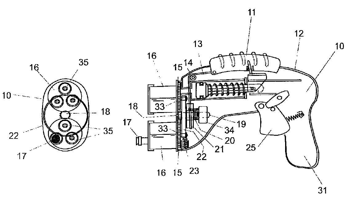
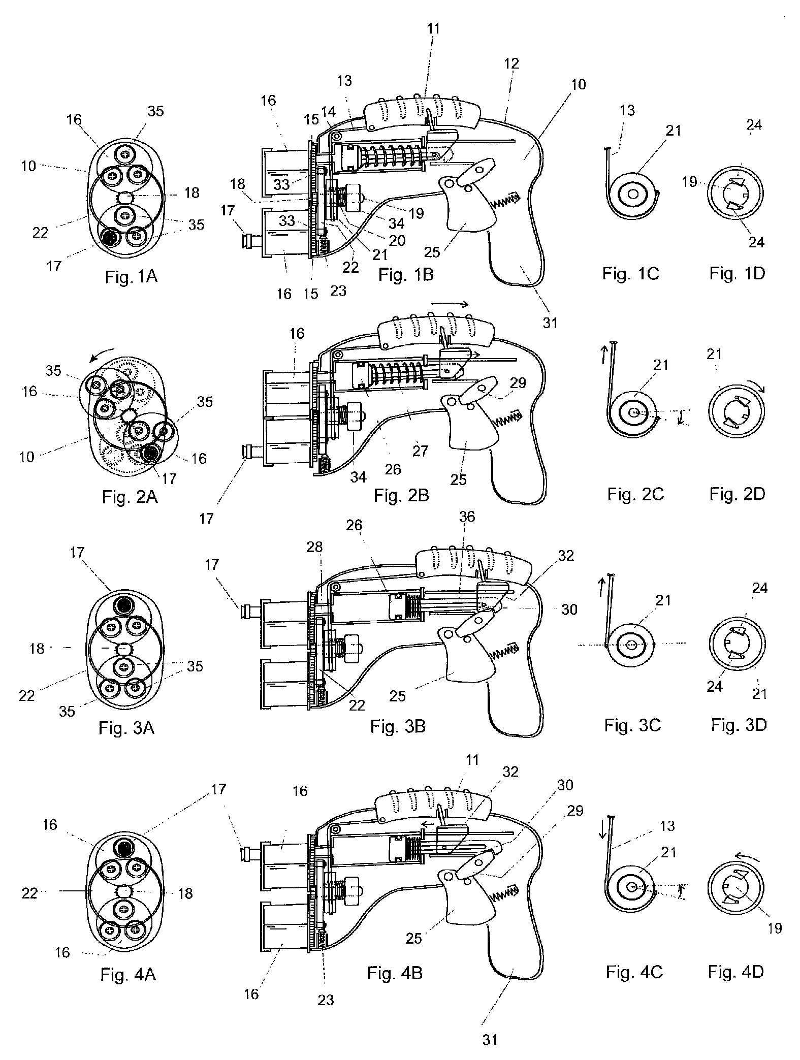
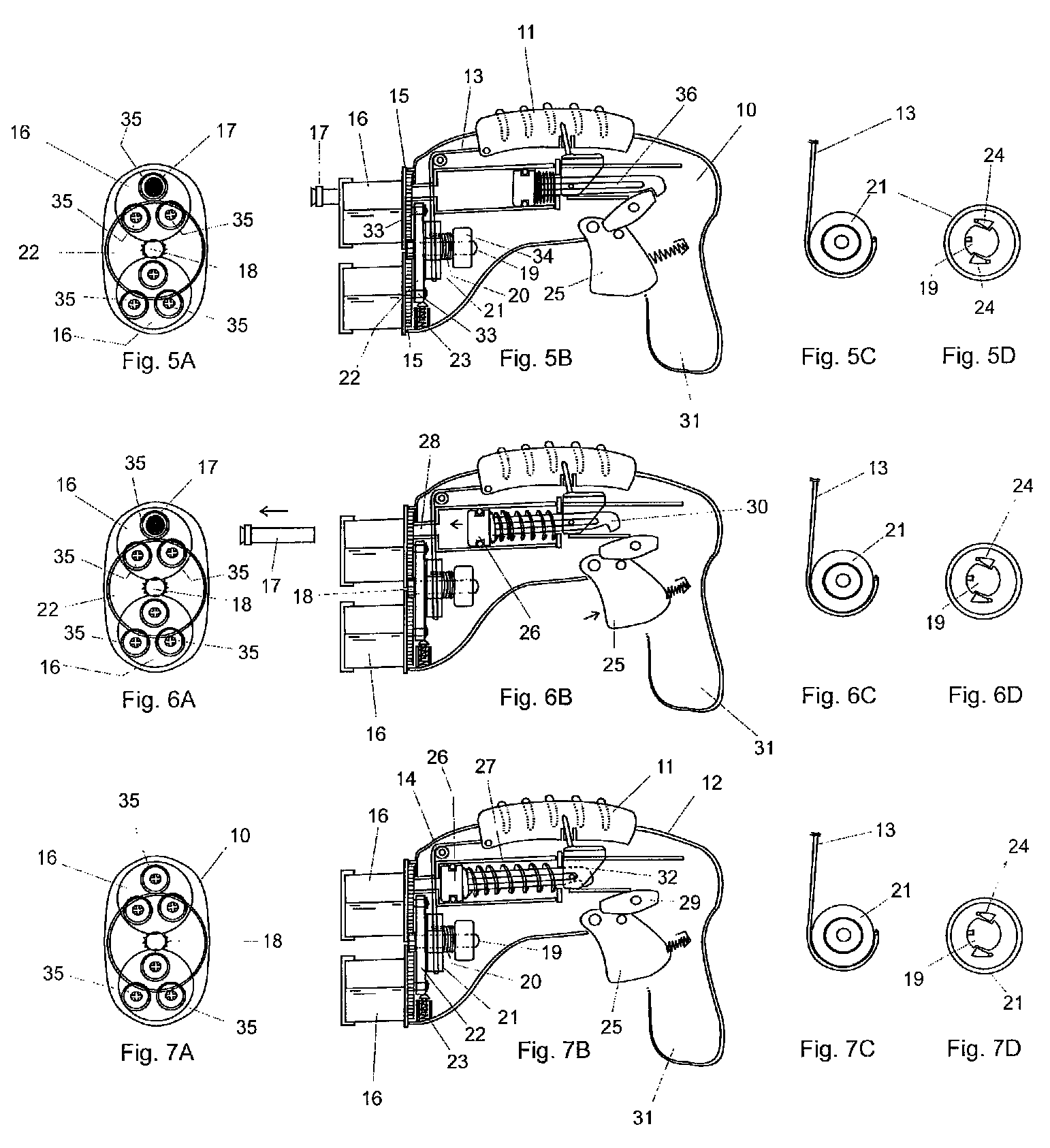
[0028]In the accompanying drawings there is depicted schematically a toy gun comprising the body 10 having a cocking handle 11 which slides upon a curved track 12 at the top of the body. A string 13 is attached to the cocking handle 11 and passes about an idling pulley 14 to an advancing pulley 21.

[0029]The advancing pulley 21 rotates about a fixed shaft 19 which is fixed to a mount 34 at its tail end. The central axis of the fixed shaft 19 extends in the longitudinal direction of the gun body 10. Also rotating about the fixed shaft 19 is a turning member in the form of a disk 22. The turning member 22 is fixed to the advancing pulley 21 so as to rotate therewith. A torsion spring 20 is wrapped about the fixed shaft 19 and has one end attached to the mount 34. The other end of the torsion spring 20 is interlocked with the advancing pulley 21. The purpose of the torsion spring 20 is to return the cocking handle 11 to its initial position.

[0030]A clutch mechanism is provided upon the ...


PUM


Abstract

A toy gun includes a body, a pinion located in the body and a turning member mounted to rotate about the pinion. A number of barrels each rotate upon the turning member at radial positions. Each barrel has a gear meshing with the pinion. Each barrel has a circular array of projectile-receiving tubes. An indexing mechanism causes the turning member to rotate about the axis whereupon the meshing interaction of the gears with the pinion causes orbital movement of the barrels about the axis as they rotate with respect to the turning member. As a result, each projectile-receiving tube is delivered to the firing position.

Description

BACKGROUND OF THE INVENTION[0001]The present invention relates to toy guns. The invention more particularly, although not exclusively, relates to toy guns for shooting a multitude of preloaded soft projectiles.[0002]Conventional toy guns designed for loading a multitude of soft projectiles or “darts” generally provide either magazine-loading, or a rotating barrel having a circular array of projectile-receiving tubes located just inboard of the barrel periphery. In this latter type, if the number of projectiles is to be high, the toy must be designed to have a barrel of large diameter to provide more loading tubes. This results in a toy gun that is wide and bulky.OBJECTS OF THE INVENTION[0003]It is an object of the present invention to overcome or substantially ameliorate the above disadvantage and / or more generally to provide an improved toy gun.DISCLOSURE OF THE INVENTION[0004]There is disclosed herein a toy gun, comprising:[0005]a body including a projectile-firing position;[0006]...

Claims


Application Information

Patent Timeline
IPC IPC(8): F41B11/00
CPCF41A21/06F41B11/646
Inventor JOHNSON, BROWNIEMA, CHOR-MING
Owner BUZZ BEE TOYS
Why Eureka
Try Eureka