
Wall rack for an office workstation

Inactive Publication Date: 2002-07-25
VITRA PATENTE AG
View PDF0 Cites 13 Cited by
  • Summary
  • Abstract
  • Description
  • Claims
  • Application Information

AI Technical Summary

Benefits of technology

[0006] Taking as the basis a wall rack such as is disclosed in WO 98 / 16135, a wall rack is proposed with a reduced use of material, which can be equipped with shelves on both sides at a selectable height, and can thus be used on both sides as an office workstation. The intention is that the wall rack will be capable of being used both for a mobile office workstation which can be varied ad hoc and as a fixed wall rack. The intention is that it will be possible to combine the wall rack in a fashion which saves space and which permits optimum configuration of working space in companies, at a fixed location, for exhibitions or congresses and for domestic use with equipment such as tables, file trolleys, cabinets and equipment boxes.

Problems solved by technology

However, the partition walls are connected to one another in such a way that a certain amount of effort is required to dismantle the device and set it up again in a modified way.
In particular in the case of situations which change ad hoc, the partition wall which is proposed here cannot be adapted in a sufficiently spontaneous way.
With the partition walls which are very simple per se it is indeed possible to deal with conditions which arise suddenly, but, owing to their simplicity, such partition walls provide only extremely limited possibilities of configuring working space in an optimum way.
This wall rack is extremely material-intensive, and equipping it with shelves or a table leaf appears to be structurally too complicated and not able to be modified to a sufficient degree.
It could be particularly unsatisfactory that the wall rack can in principle be used on only one side; for use on both sides it is necessary to place a second wall rack at its rear.

Method used


Image

  • Wall rack for an office workstation
  • Wall rack for an office workstation
  • Wall rack for an office workstation

Examples


Embodiment Construction

[0027] The detailed description of a preferred exemplary embodiment of the wall rack according to the invention with alternative equipment variations is given below with reference to the appended drawings.

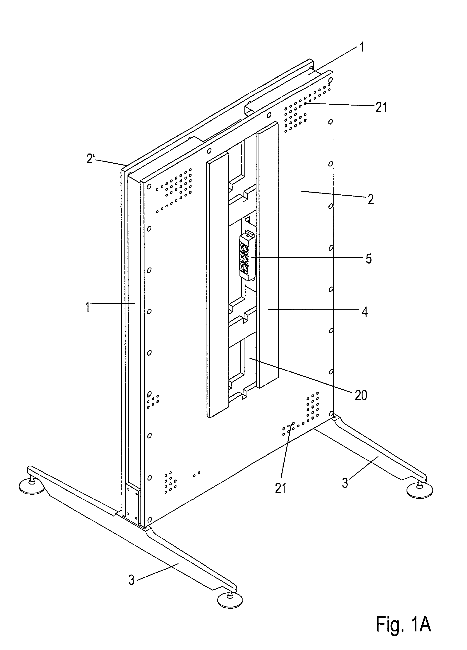
FIG. 1A

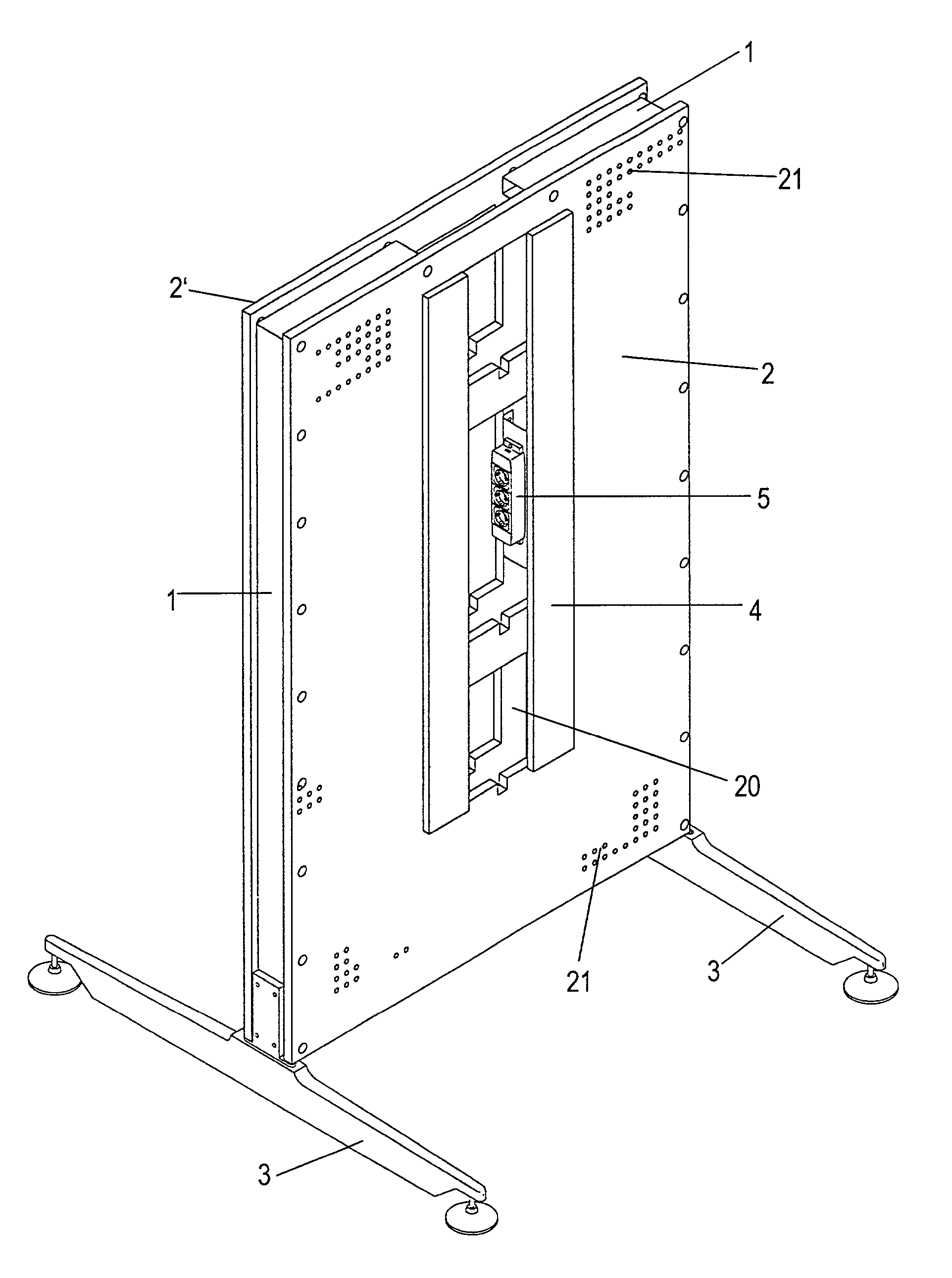
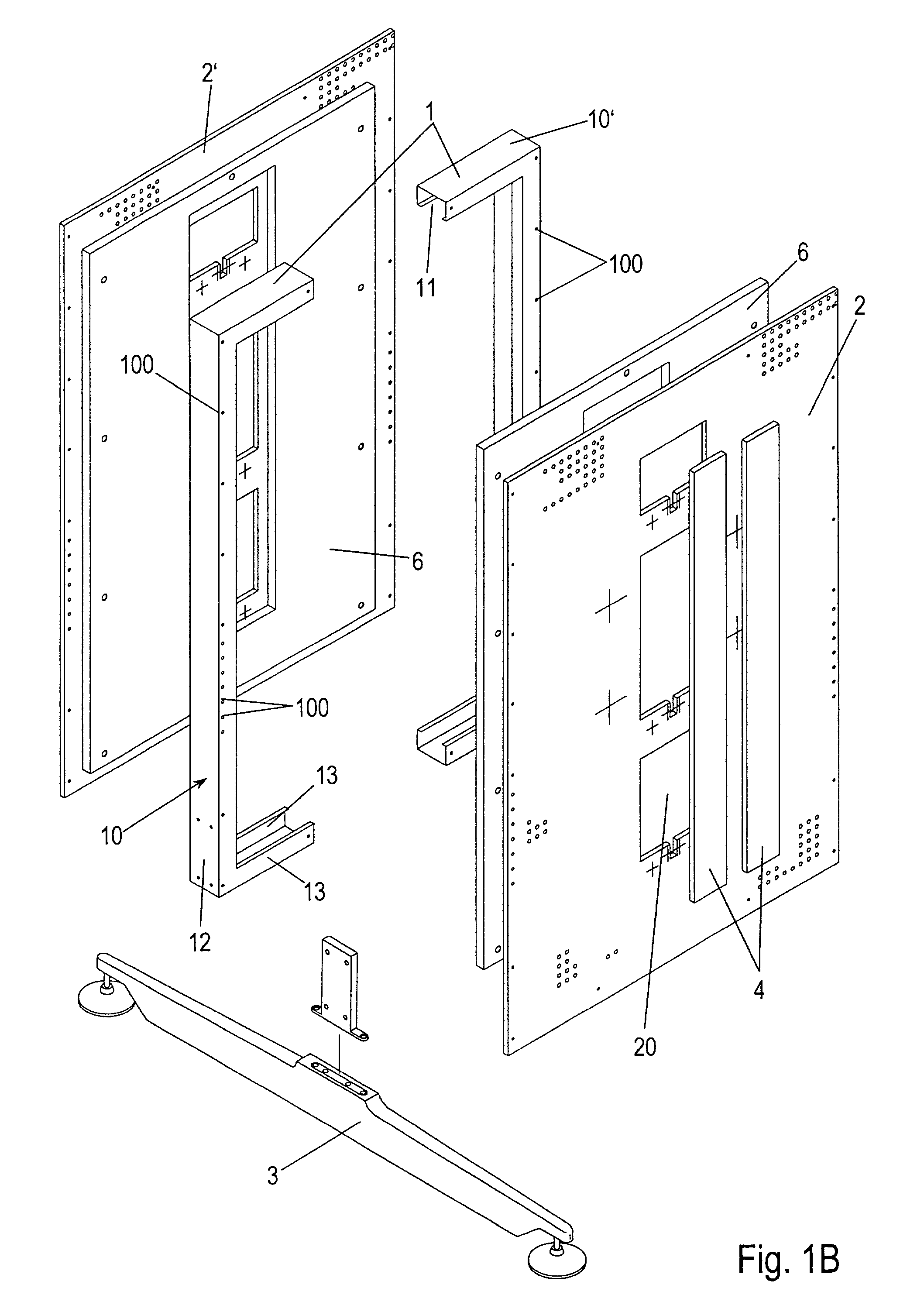
[0028] The wall rack which is initially unequipped is composed essentially of an upright base frame 1 onto which a front panel 2,2' is fitted from each side. In a freestanding arrangement, the wall rack has two wall rack feet 3 which are placed on the floor and are attached to the bottom of the base frame 1. An opening 20 for feeding through power supply leads and communication leads to the equipment set up in front of the wall rack is provided in each front panel 2,2'. The opening 20 is divided here into three sections--corresponding to the three planes for the shelves which are to be arranged. Internally, the wall rack has an electric socket unit 5 which is manually accessible through the opening 20 and has the purpose of connecting power supply leads and communication lea...


PUM


Abstract

The wall rack which is designed for an office workstation, in particular a PC workstation, in a freestanding mobile embodiment or with fixed installation comprises essentially an upright base frame (1,10,10') onto which a front panel (2,2') is fitted on each side. The shelves (7,8) of various shapes and dimensions in the form of storage shelves (7) or work surfaces (8) which can withstand larger loads can be arranged and rearranged at selected heights on one or both front panels (2,2'). Through a subdivided opening (20) in the front panels (2,2'), which can be manually accessed by means of flaps (4) which can be pivoted upward, it is possible to access an electric socket unit for supplying power and / or for connecting communication leads for the equipment positioned in front of the wall rack. The storage shelves (7) are mounted in a detachable fashion by means of supporting bars (71) which are plugged in to socket holders (73) and mounting pins which are mounted on the front panels (2,2'). The work surfaces (8) rest on brackets which are pushed onto bracket holders which are also connected to the base frame (1,10,10') through the front panels

Description

[0001] The present invention relates to a wall rack for an office workstation, in particular a PC workstation, which is completely mobile in a freestanding embodiment and can be at least temporarily fixed in place when mounted against a rear panel. The wall rack can be used in permanent offices of companies, at trade fairs, at conferences or in the domestic sphere. Tables, file trolleys, cabinets and equipment boxes can be placed against the wall rack.PRIOR ART[0002] EP 0 447 961 A2 discloses an office device which can be combined in accordance with the modular principle, can be configured in various ways, has various items of furniture and also comprises partition walls. Diverse, individually adapted solutions can be produced using the individual system components. However, the partition walls shown only have the function of dividing up space in order to form delimited work areas. However, the partition walls are connected to one another in such a way that a certain amount of effor...

Claims


Application Information

Patent Timeline
IPC IPC(8): A47B21/00A47B47/00A47B47/02A47B57/06A47B57/18A47F5/10
CPCA47B21/00A47B21/06A47B47/00A47B47/022A47B57/06A47B57/18A47B2200/0076A47F5/105
Inventor BRAUNING, EGON
Owner VITRA PATENTE AG
Learn More