Wire guides for a scalpel

a scalpel and guidewire technology, applied in the field of scalpel guide system, can solve the problems of affecting the smoothness of the scalpel, the tip of the medical device can flare and bind at the skin surface, and the tubular medical device is too large and pliable to easily pass through the skin and tissues,

Active Publication Date: 2008-03-11
HEPPLER J SCOTT
View PDF7 Cites 19 Cited by
  • Summary
  • Abstract
  • Description
  • Claims
  • Application Information

AI Technical Summary

Problems solved by technology

The elongated, tubular medical device can be too large and too pliable to easily pass over the guidewire, through the needle hole made in the skin and tissues and into the desired body cavity or lumen.
If the nick is made away from the entry site of the wire or is not sufficiently deep, the medical device will not pass over the guidewire and through the skin and tissues easily.
If excessive force is used the tip of the medical device can flare and bind at the skin surface.
In urgent settings, with poorly positioned patients, in poorly lighted rooms, a precisely placed skin nick can require significant concentration at a time when there are other pressing issues with the patient.
This device has several perceived weaknesses.
Another disadvantage of the Samuels et al. device is that is utilizes a custom blade that has a central lumen.
Such a blade would be relatively expensive to manufacture.
However, like Samuels et al., discussed above, both of these devices require the operator to thread the guidewire through a tubular member, very near surgical blades.

Method used


Image

  • Wire guides for a scalpel
  • Wire guides for a scalpel
  • Wire guides for a scalpel

Examples


Embodiment Construction

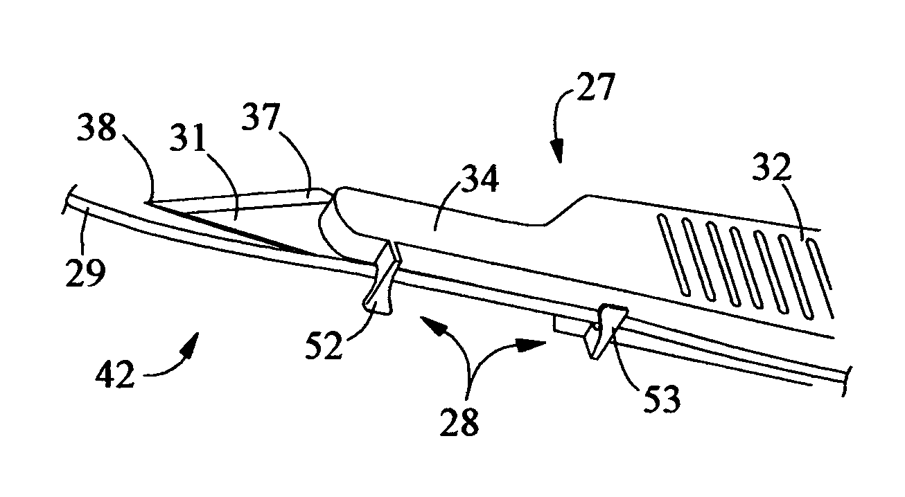
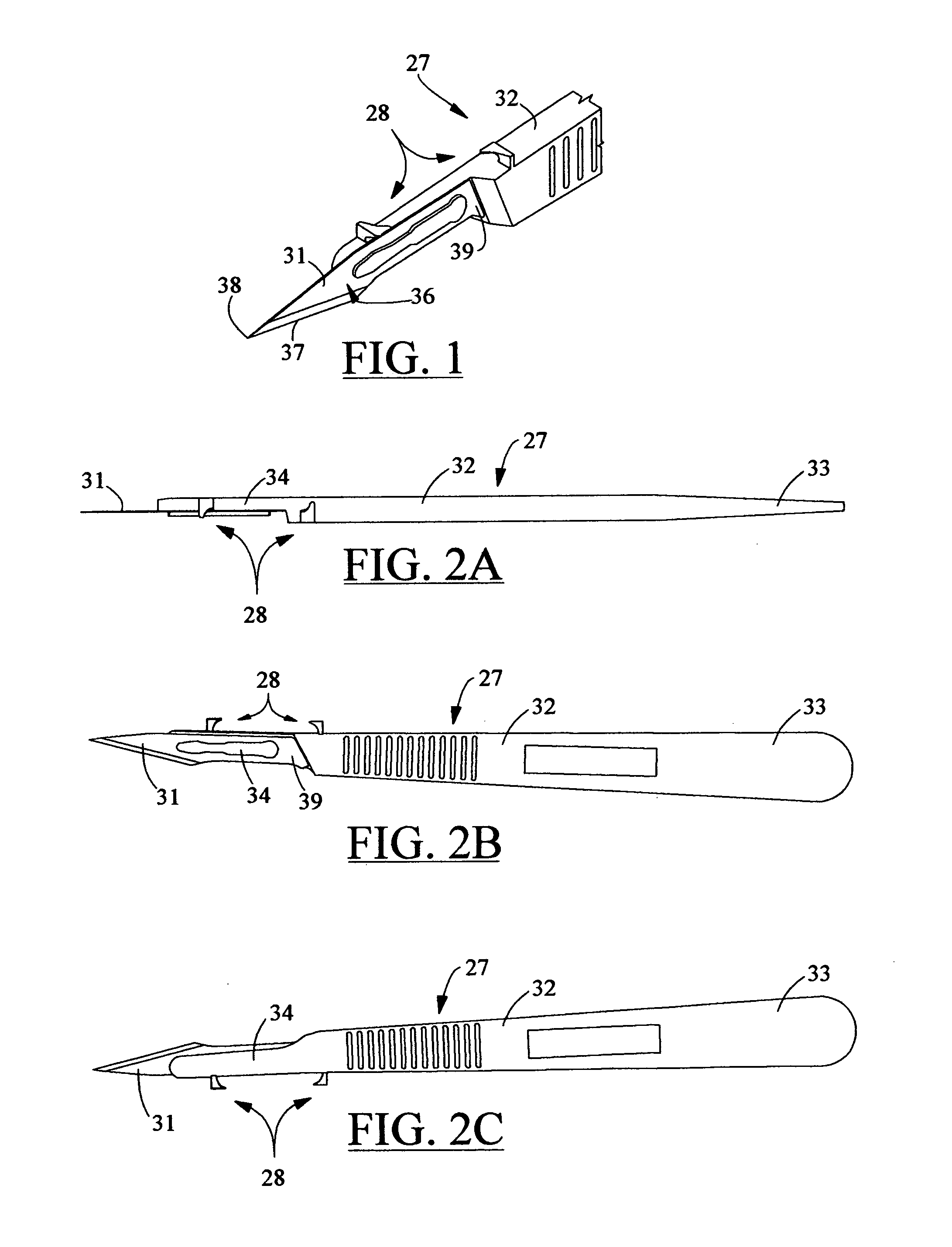
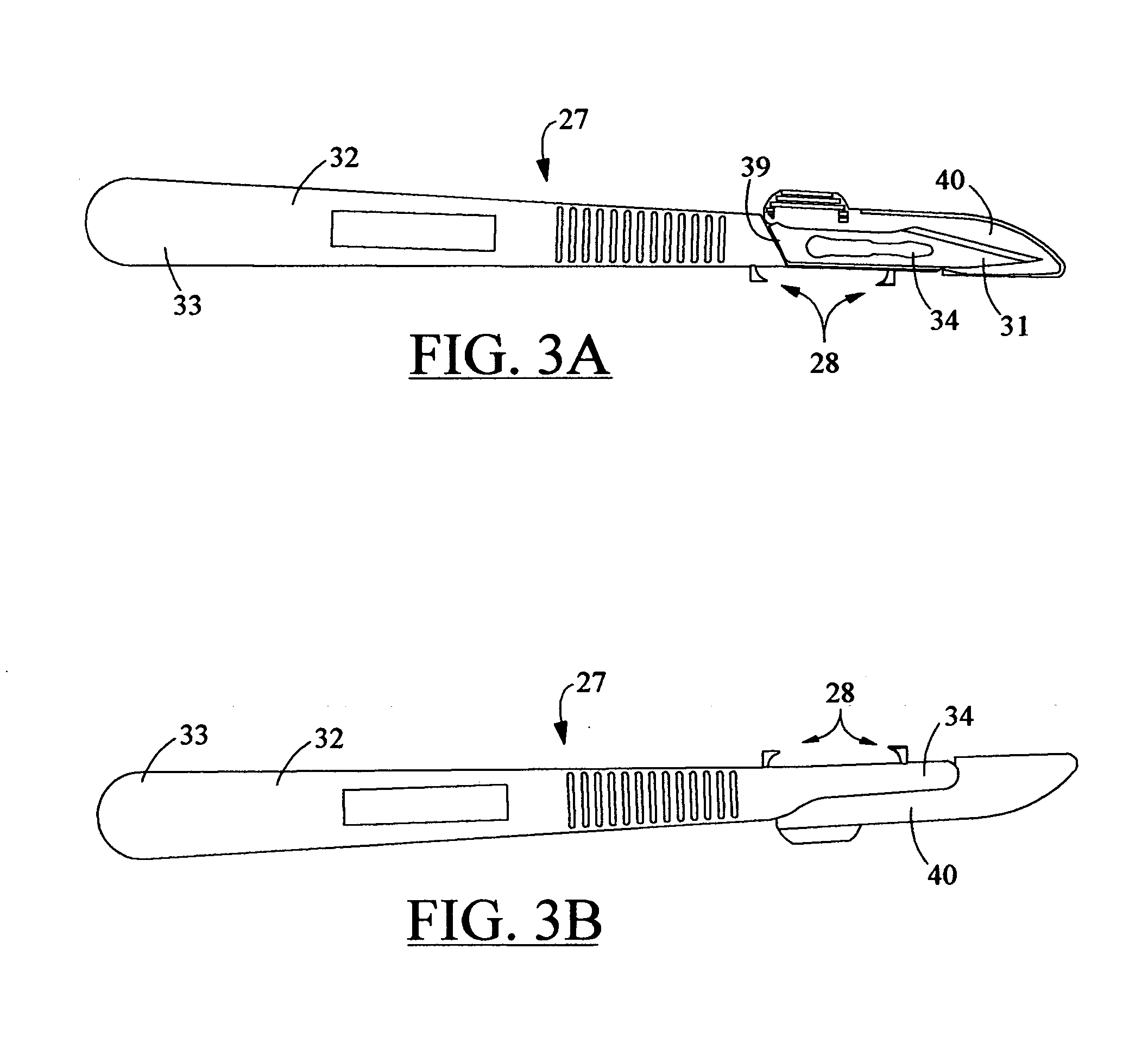
[0050]The present invention provides wire guides for a scalpel, and specifically for a system of guided and controlled movement of the scalpel along a wire. The scalpel guiding system 25 is shown in FIGS. 1 through 22C. The scalpel guiding system is especially useful as an enhancement to the “Seldinger technique.” As discussed in the foregoing section, the Seldinger technique is a common surgical procedure employed by a user 26 of a scalpel 27, for the percutaneous placement of elongated, tubular devices, with the aid of a guidewire or a wire 29.

[0051]As detailed in FIGS. 1 and 2, the scalpel guiding system 25 preferably includes a pair of wire guides 28, each extending from the scalpel 27. For the present invention, the scalpel can be any knife-like surgical device, conventionally including a blade 31 attached to a handle 32. The handle can be formed of a plastic or a metal. Plastic handles are typically employed in disposable scalpel designs, and metal handles utilized in reusable...


PUM


Abstract

A scalpel guide system for any bladed surgical instrument. A pair of wire guides attach to a scalpel, for controlled travel of the scalpel along the wire. The wire guides of the scalpel guiding system are especially useful as an enhancement to the “Seldinger technique,” a common surgical procedure employed for the percutaneous placement of elongated, tubular devices, with the aid of a guidewire or a wire. The scalpel can be any knife-like surgical device, conventionally including a blade attached to a handle. The scalpel guiding system preferably includes a pair of wire guides, each extending from the blade of the scalpel, or alternatively the handle of the scalpel. The scalpel can be disposable, as can the blade, independent of the scalpel. The wire can be any guidewire or filament, as conventionally employed in surgical techniques that involve the insertion of such a wire or strand. The wire is engageable by the scalpel mounted pair of wire guides. This engagement allows the user or surgeon to move the scalpel along the wire in a controlled and guided manner, for precise cutting or incising, as required for the needed procedure or operation.

Description

TECHNICAL FIELD[0001]The invention relates to a scalpel guide system for any bladed surgical instrument, and more particularly to a set of wire guides attached to a scalpel, for controlled travel of the scalpel along the wire.BACKGROUND OF THE INVENTION[0002]There are many percutaneous medical devices that function to evacuate air or fluid from body cavities. Conversely, other such devices function to administer a substance, such as a drug, into the body cavity or into a vascular lumen. Most of these percutaneous devices are elongated and tubular, sharing a common method of placement over a guide-wire. This common method is known as the “Seldinger technique.”[0003]The Seldinger technique has revolutionized the practice of medicine by allowing procedures that were previously done with “open” surgical technique to be performed with “closed,” percutaneous technique. As is evident from the following description of the Seldinger technique, the “closed” percutaneous method results in an i...

Claims


Application Information

Patent Timeline
Patent Type & Authority Patents(United States)
IPC IPC(8): A61B17/32A61B17/34
CPCA61B17/32093A61B17/3213A61B17/3415A61B2017/3405A61B2017/320052A61B2017/32113A61B2017/22039
Inventor HEPPLER, J. SCOTT
Owner HEPPLER J SCOTT
Why Eureka
Try Eureka