Endoscopic suturing system

a suturing system and endoscope technology, applied in the direction of mechanical equipment, surgical staples, applications, etc., can solve the problems of inability to provide transmission of large force and large opening/closing angle of treatment device for endoscope, and achieve the effect of increasing the opening/closing angle and producing a large for

Active Publication Date: 2008-03-18
OLYMPUS CORP +1
View PDF4 Cites 113 Cited by
  • Summary
  • Abstract
  • Description
  • Claims
  • Application Information

AI Technical Summary

Benefits of technology

[0006]The present invention has been made in view of the above described circumstance. It is an object of the present invention to provide

Problems solved by technology

However, the posts and devises interfere with each other, whereby an angle that can be formed between the devises is restricted to an angle of about 90 degr

Method used


Image

  • Endoscopic suturing system
  • Endoscopic suturing system
  • Endoscopic suturing system

Examples


12th embodiment

[0398]FIG. 112 to FIG. 122 show the 12th embodiment.

(Arrangement)

[0399]The 12th embodiment differs from the 10th embodiment in the following points.

[0400]As shown in FIG. 113, the interval between pins 329 and 330 of a suturing device 374 of the 12th embodiment is larger than that between the pins 235 and 236 in the 10th embodiment. In addition, the interval between the pin 329 and a pin 331, the interval between the pin 330 and a pin 332, the interval between the pin 331 and a pin 333, and the interval between the pin 332 and the pin 333 are also larger than those in the 10th embodiment. As in the 11th embodiment, this arrangement allows a first active member 313 to make a larger rotational movement, and also can increase the puncturing force acting on a removable needle 213 fixed to a needle holding member 336.

[0401]As shown in FIG. 114 and FIG. 117, a second active member 314 can rotate about the pin 330. A pipe 381 is rotatably fitted on part of the pin 330, and a spring 334 is ...

15th embodiment

[0424]FIG. 129 to FIG. 143 show the 15th embodiment.

(Arrangement)

[0425]The 15th embodiment is configured to continuously suture the tissue by using the suturing device exemplified by the fourth to 14th embodiments.

[0426]As shown in FIG. 129, in the 15th embodiment, each of the needle holders 216, 336, and 357 in the fourth to 13th embodiments are modified into a needle holder 396. Likewise, the pre-knot cartridge 365 is modified into a pre-knot cartridge 407, and each of the needle-catching-devices 212 and 283 is modified into a needle-catching-device 390. The pre-knot cartridge 407 is comprised of a removable needle 389, thread 391, pre-knot 397, and the like. The removable needle 389 is comprised of a needle 392, slide member 393, spring 399, lock members 394 and 395, and the like. As in the case of the removable needle 213 in the 10th embodiment, the thread 391 is fixed to the needle 392 with a stopper 408 formed on the thread. The slide member 393 and needle 392 are slidably fit...

16th embodiment

[0438]FIG. 144 to FIG. 163 show the 16th embodiment.

(Arrangement)

[0439]The 16th embodiment differs from the 11th embodiment in the following points.

[0440]Since the length of a spring 432 is decreased as compared with that in the 11th embodiment shown in FIG. 102, a projection member 466 formed on the distal end of a holding member 292, which interferes with the field of view of an endoscope, is omitted. This improves the field of view in a suturing operation (see FIG. 145).

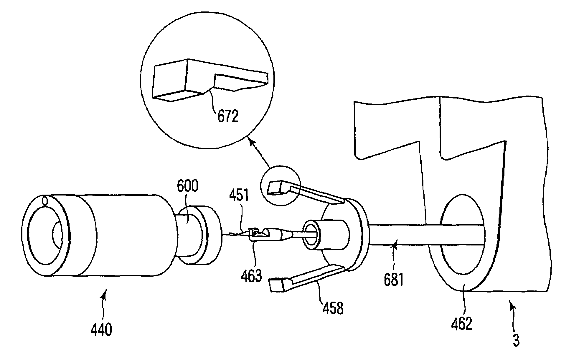
[0441]In this embodiment, a suturing operation is performed by using an end loop cartridge 440 shown in FIG. 146 and FIG. 158 in place of the pre-knot cartridge 365 in the 11th embodiment. The end loop cartridge 440 is comprised of a removable needle 441, suture thread 442, needle lock mechanism 475, casing member 446, releasing member 447, elastic member 448, rigid member 449, and the like.

[0442]Referring to FIG. 146 and FIG. 158, the suture thread 442 fixed to the removable needle 441 is pressed into the elastic...


PUM


Abstract

An endoscopic treatment device is used with an endoscope. This treatment device includes a transmission member with a flexible structure having a distal end portion to be inserted into a body and can be operated outside the body, a push rod coupled to the distal end portion, and first and second connecting members rotatably coupled to the push rod. The treatment device further includes first and second arm members rotatably coupled to the distal end portion of the connecting member, a holding member rotatably holding the respective arm at a predetermined interval therebetween, and first and second actuating members integrally formed with the arm members and can open/close when the transmission member actuates the first and second connecting members and the first and second arm members through the push rod. This device also includes a needle mounted on at least one of the first and second actuating members.

Description

CROSS-REFERENCE TO RELATED APPLICATIONS[0001]This is a Continuation-in-Part application of U.S. patent application Ser. No. 10 / 353,866, filed Jan. 29, 2003, the entire contents of which are incorporated herein by reference.[0002]This application claims the benefit of U.S. Provisional Application No. 60 / 352,728, filed Jan. 30, 2002; and No. 60 / 430,259, filed Dec. 2, 2002.BACKGROUND OF THE INVENTION[0003]The present invention relates to a treatment device which can be inserted into a body together with an endoscope. U.S. Pat. No. 5,171,258 (Symbiosis Co., Ltd.) discloses a medical instrument that is applicable to a surgical operation using a laparoscope. This medical instrument comprises a pair of posts for supporting a pair of devises in order to produce a large force required to grip a thick tissue. However, the posts and devises interfere with each other, whereby an angle that can be formed between the devises is restricted to an angle of about 90 degrees.[0004]On the other hand, w...

Claims


Application Information

Patent Timeline
IPC IPC(8): A61B17/04A61B17/06A61B17/064
CPCA61B17/0467A61B17/0469A61B17/0483A61B17/0487A61B17/0625A61B1/018A61B17/0485A61B17/0493A61B17/06066A61B17/0643A61B2017/00296A61B2017/0034A61B2017/0445A61B2017/0448A61B2017/045A61B2017/0458A61B2017/0464A61B2017/0472A61B2017/0474A61B2017/0475A61B2017/0477A61B2017/0488A61B2017/06019A61B2017/06028A61B2017/06042A61B2017/06057
Inventor TAKEMOTO, SHOTAROYAMAMOTO, TETSUYAKAWASHIMA, KOICHICHUNG, SYDNEY SHEUNG CHEEMATSUI, RAIFU
Owner OLYMPUS CORP
Why Eureka
Try Eureka