Maneuvering system having inner force sense presenting function

a technology of inner force and manipulator, applied in the field of manipulator, can solve the problems of insufficient movable range, difficult to freely approach the site to be treated, bulky apparatus, etc., and achieve the effects of reducing the weight of the slave manipulator, reducing the size of the grip unit, and easy disinfection of the grip uni

Active Publication Date: 2014-11-25
RIVERFIELD INC
View PDF12 Cites 4 Cited by
  • Summary
  • Abstract
  • Description
  • Claims
  • Application Information

AI Technical Summary

Benefits of technology

[0017]This makes it not necessary in the master manipulator to compensate for the dynamics and the self-weight of the master manipulator in the motion range of a user, allowing highly accurate, broadband positional control, which is specific to an electrically-driven system, and in the slave manipulator, nonlinearity characteristics specific to a pneumatically-driven system presents passive softness, provides a high mass-to-output ratio, and produces a large force.
[0038]Furthermore, the manipulation system is characterized in that the master manipulator includes a 3-DOF translation unit and a 4-DOF orientation unit connected to the translation unit, and the slave manipulator includes a 3-DOF holding unit and a 4-DOF grip unit held by the holding unit. Such a configuration allows the motion of the human hand on the master manipulator side to be reproduced on the slave manipulator side. Further, the manipulation system is characterized in that the translation unit, the orientation unit, the holding unit, and the grip unit are configured as a delta mechanism, a gimbal mechanism, a combination of a parallel link mechanism and a gimbal mechanism, and a wire mechanism, respectively. The master manipulator and the slave manipulator are thus configured differently from each other, so that the shapes thereof can be optimized in terms of operability. Further, the manipulation system is characterized in that the grip unit includes pneumatic rotary actuators and wires connected to the pneumatic actuators, and the grip unit is driven by pulling motions of the wires in response to the motions of the pneumatic actuators. The grip unit can therefore directly transmit the swing motions of the pneumatic actuators, so that the weight of the slave manipulator can be reduced.
[0039]Further more, the manipulation system is characterized in that the force acting on the grip unit is estimated from the drive forces of the pneumatic actuators by making use of the back drivability thereof. No force sensor is therefore required on the grip unit, thereby providing advantages of reducing the size of the grip unit, making disinfection of the grip unit easy, and eliminating the need for calibration of the grip unit. The manipulation system is characterized in that compliance-based control is applied to the slave manipulator. Therefore, the slave manipulator will not produce an excessive force.
[0040]Further, the manipulation system is characterized in that position-based impedance control in which a force control loop includes a motion control loop is applied to the master manipulator, and force-based impedance control in which a motion control loop includes a force control loop is applied to the slave manipulator. Therefore, the slave manipulator can be stably operated by imparting a moderate viscosity effect to the master manipulator. Further, the manipulation system is characterized in that automatic operation of the slave manipulator that follows manual operation of the master manipulator is bilaterally controlled by means of wired communication. The master manipulator can therefore remotely operate the slave manipulator by means of the Internet.

Problems solved by technology

However, since the operator moves the forceps or other related tools using the abdominal wall as a pivotal point, sufficient degrees of freedom are not provided at the tip of the forceps and hence it is not easy to freely approach the site to be treated.
However, such a multi-DOF forceps system using electric actuators to drive the master and slave portions not only cannot feed a minute force back to the operator because of a high reduction ratio, but also has an insufficient movable range and results in a bulky apparatus.
Further, attaching a force sensor to the forceps is not an easy task in consideration of practical factors, such as reduction in size, sterilization, and calibration.
However, in the multi-DOF forceps systems proposed in the above mentioned study, the forceps manipulator has only three degrees of freedom, which does not allow the motion of the human hand to be reproduced.
In the multi-DOF forceps systems described in the non-patent documents 1 and 2, the forceps manipulator includes a mechanism that converts the linear motion of a pneumatic cylinder into rotational motion, so that reduction in weight of the forceps manipulator is difficult to achieve.
Further, the master and the slave portions are configured in the same manner (both are controlled pneumatically), which does not necessarily provide an optimum structure in terms of operability.

Method used


Image

  • Maneuvering system having inner force sense presenting function
  • Maneuvering system having inner force sense presenting function
  • Maneuvering system having inner force sense presenting function

Examples


Embodiment Construction

[0055]An embodiment of the invention will be described with reference to the drawings. The embodiment, which will be described below, does not limit the inventive aspects according to the claims, and of all the combinations of the features described in the embodiment are not necessarily essential in providing means for solving the problems.

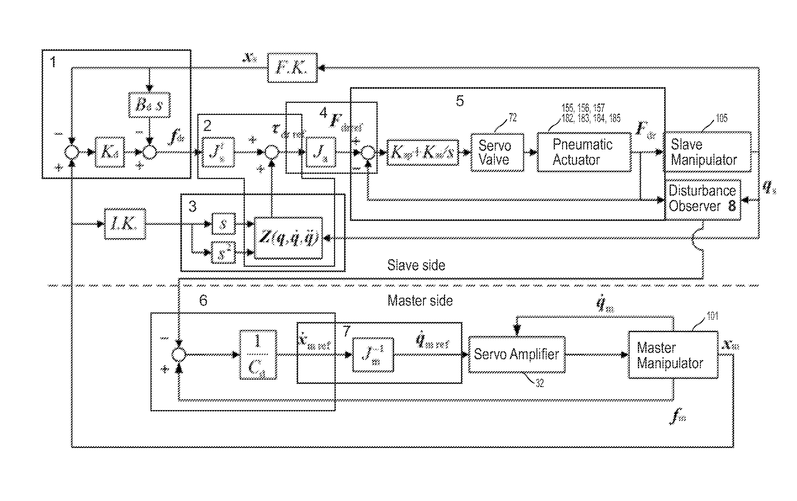
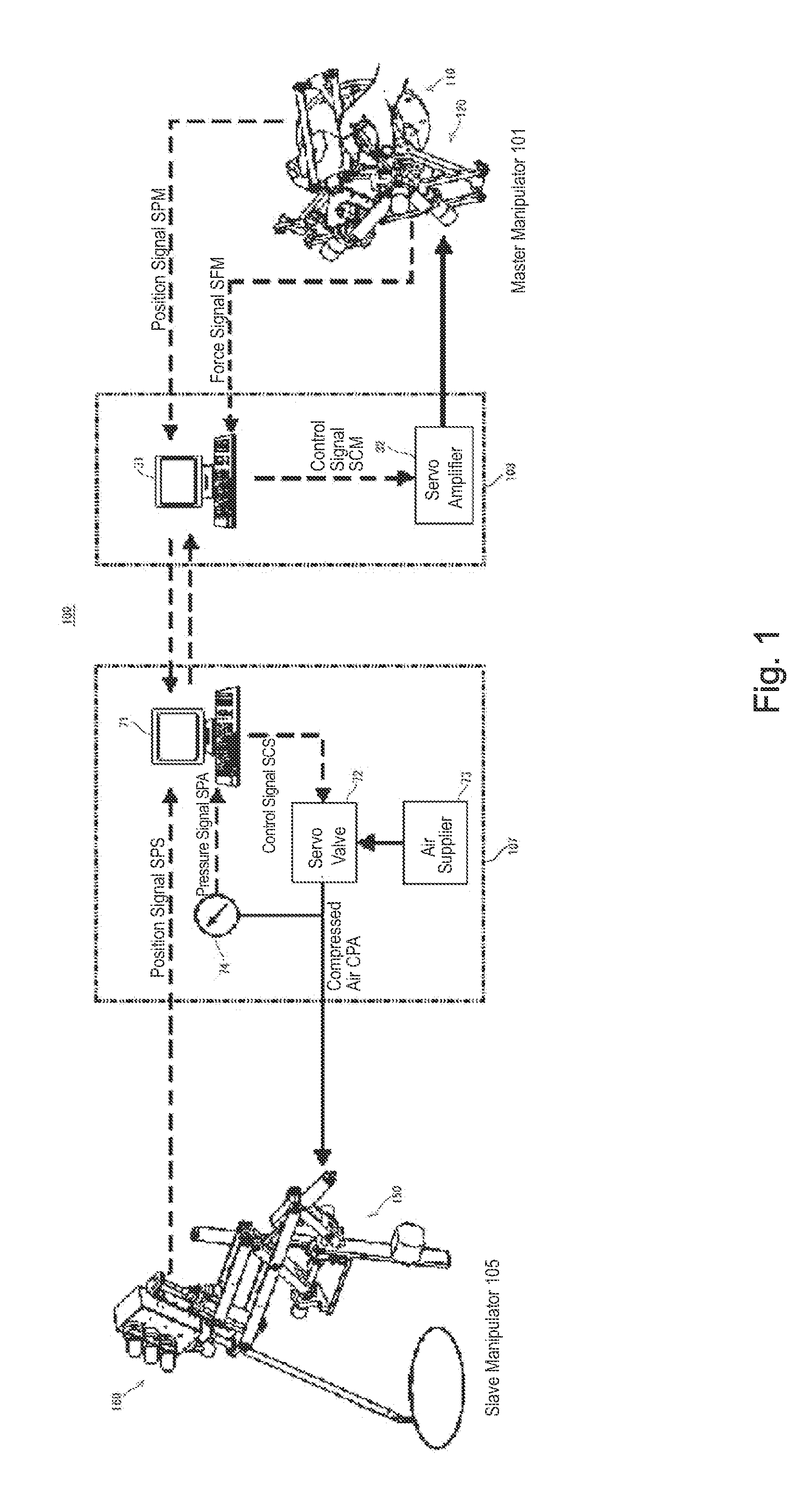
[0056]FIG. 1 is a schematic configuration diagram showing a manipulation system having a force feedback capability according to an embodiment of the invention. The manipulation system having a force feedback capability is a multi-DOF forceps system 100 including a master manipulator 101, a master controller 103, a slave manipulator 105, and a slave controller 107. The multi-DOF forceps system 100 is a remote manipulation system in which automatic operation of the slave manipulator 105 that follows manual operation of the master manipulator 101 is remotely controllable by means of wired communication between the master controller 103 and the slave ...


PUM


Abstract

A compact, lightweight manipulation system that excels in operability and has a force feedback capability is provided. When automatic operation of a slave manipulator 105 that follows manual operation of a master manipulator 101 is bilaterally controlled by means of communication, the force acting on the slave manipulator is fed back to the master manipulator by operating the master manipulator primarily under electrically-driven speed control and the slave manipulator primarily under pneumatically-driven force control. Therefore, in the master manipulator, it is not necessary to compensate for the dynamics and the self-weight of the master manipulator in the motion range of a user, allowing highly accurate, broadband positional control, which is specific to an electrically-driven system, and in the slave manipulator, nonlinearity characteristics specific to a pneumatically-driven system presents passive softness, provides a high mass-to-output ratio, and produces a large force.

Description

CROSS-REFERENCE TO RELATED APPLICATIONS[0001]This application is a continuation-in-part application claiming priority under 35 U.S.C. 120 from co-pending U.S. patent application Ser. No. 12 / 529,515 entitled “MANEUVERING SYSTEM HAVING INNER FORCE SENSE PRESENTING FUNCTION”. The entire disclosure of the aforesaid application is hereby incorporated by reference herein.FIELD OF THE INVENTION[0002]The present invention relates to a manipulation system in which automatic operation of a slave manipulator that follows manual operation of a master manipulator is bilaterally controllable by means of communication, and particularly to a manipulation system having a force feedback capability.BACKGROUND OF THE INVENTION[0003]In recent years, surgical operations have been widely practiced in the form of endoscopic surgery to improve QOL (Quality of Life), such as reduction in patient's pain, hospitalization period, and size of the scar associated with the surgery. Endoscopic surgery is performed ...

Claims


Application Information

Patent Timeline
Patent Type & Authority Patents(United States)
IPC IPC(8): B66C1/42B25J17/00G06F19/00B25J18/00B25J17/02B25J18/02B66B21/00
CPCB25J3/04Y10S901/22Y10S901/34B25J13/025B25J9/1689B25J18/02Y10T74/20305
Inventor KAWASHIMA, KENJITADANO, KOTARO
Owner RIVERFIELD INC
Why Eureka
Try Eureka