Apparatus and method for identifying a loss of a current transformer signal in a power system

a technology of current transformer and signal, applied in the direction of circuit-breaking switches, electrical apparatus, circuit-breaking switches for excess current, etc., can solve problems such as relay operation, protective devices may incorrectly “perceive” short circuits, and protective devices can potentially misopera

Active Publication Date: 2008-03-18
SCHWEITZER ENGINEERING LABORATORIES
View PDF19 Cites 26 Cited by
  • Summary
  • Abstract
  • Description
  • Claims
  • Application Information

AI Technical Summary

Benefits of technology

[0012]In accordance with the invention, an apparatus is provided in a protective device for identifying a loss of a specific current transformer (CT) signal of a plurality of CT signals. The plurality of CT signals is provided to the protective device by a corresponding plurality of CTs coupling the protective device to at least one protection zone of a power system. The apparatus includes a number of first logic circuits. Each of the first logic circuits is configured to provide a binary control signal pair having a first binary control signal and a second binary control signal in response to comparisons of a first RMS value of a digitized current sample stream of a corresponding CT signal sampled at first time to a second RMS value of the digitized current sample stream sampled at a second time. The apparatus also includes at least one second logic circuit operatively coupled to the first logic circuits and configured to provide a third binary control signal in response to receipt of the plurality of binary control signal pairs. During operation, a first value for only one of the plurality of first binary control signals and a second value for all of the second binary control signals and the first value for the third binary control signal for a pre-defined time interval indicates the loss of the specific CT signal corresponding to the first logic circuit providing the first binary control signal having the first value, and prevents issuance of a trip signal of the protective device

Problems solved by technology

Due to their integral role in the power system, if a defective current transformer delivers an incorrect or errant secondary current to a protective device (e.g., a current differential relay, an overcurrent distance relay), problems may arise in relay operation.
Because the incorrect or errant secondary current is not reflective of the actual operate current, a circuit breaker in the protection zone may fail to trip in the event of a short circuit in the protection zone, or an erroneous trip may occur when no short circuit exists.
In other words, the protective device may incorrectly “perceive” a short circuit or other fault in the protection zone when the errant current is actually due to a current transformer problem.
In such cases, the protective device can potentially misoperate.
For example, in a current differential relay, the missing current creates a false “high” operate current that may potentially exceed the trip threshold.
As a result, an unwanted trip signal may be issued, despite the absence of a short circuit in the protection zone.
Various prior art algorithms have attempted to detect when a lost CT signal is present, however all have limitations.
Further, while a lost CT signal may be detected using such a prior art algorithm, the specific lost CT signal from among a number of CT signals is not identified.
As a result, its associated specific current transformer can not be identified.

Method used


Image

  • Apparatus and method for identifying a loss of a current transformer signal in a power system
  • Apparatus and method for identifying a loss of a current transformer signal in a power system
  • Apparatus and method for identifying a loss of a current transformer signal in a power system

Examples


Embodiment Construction

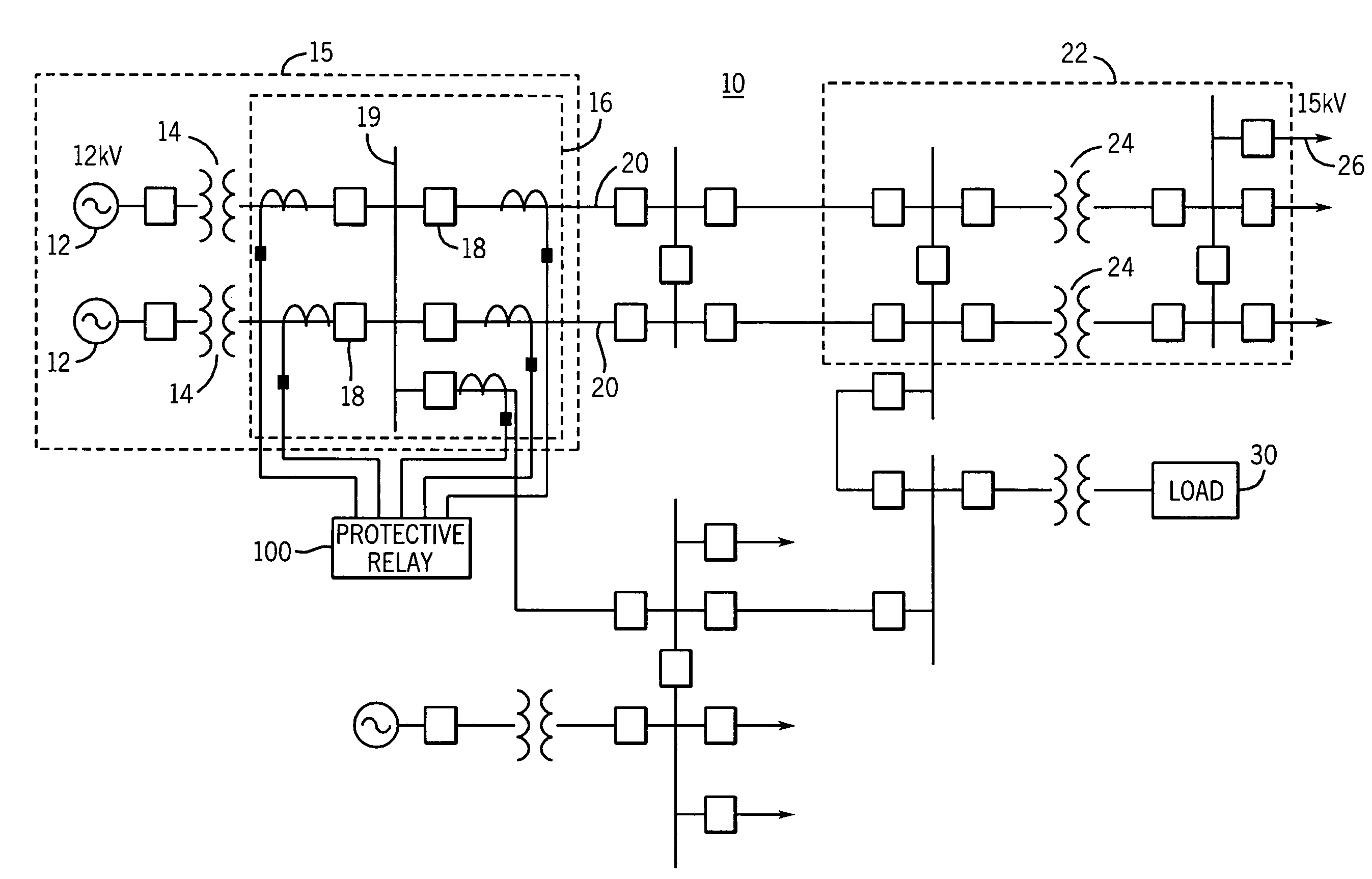
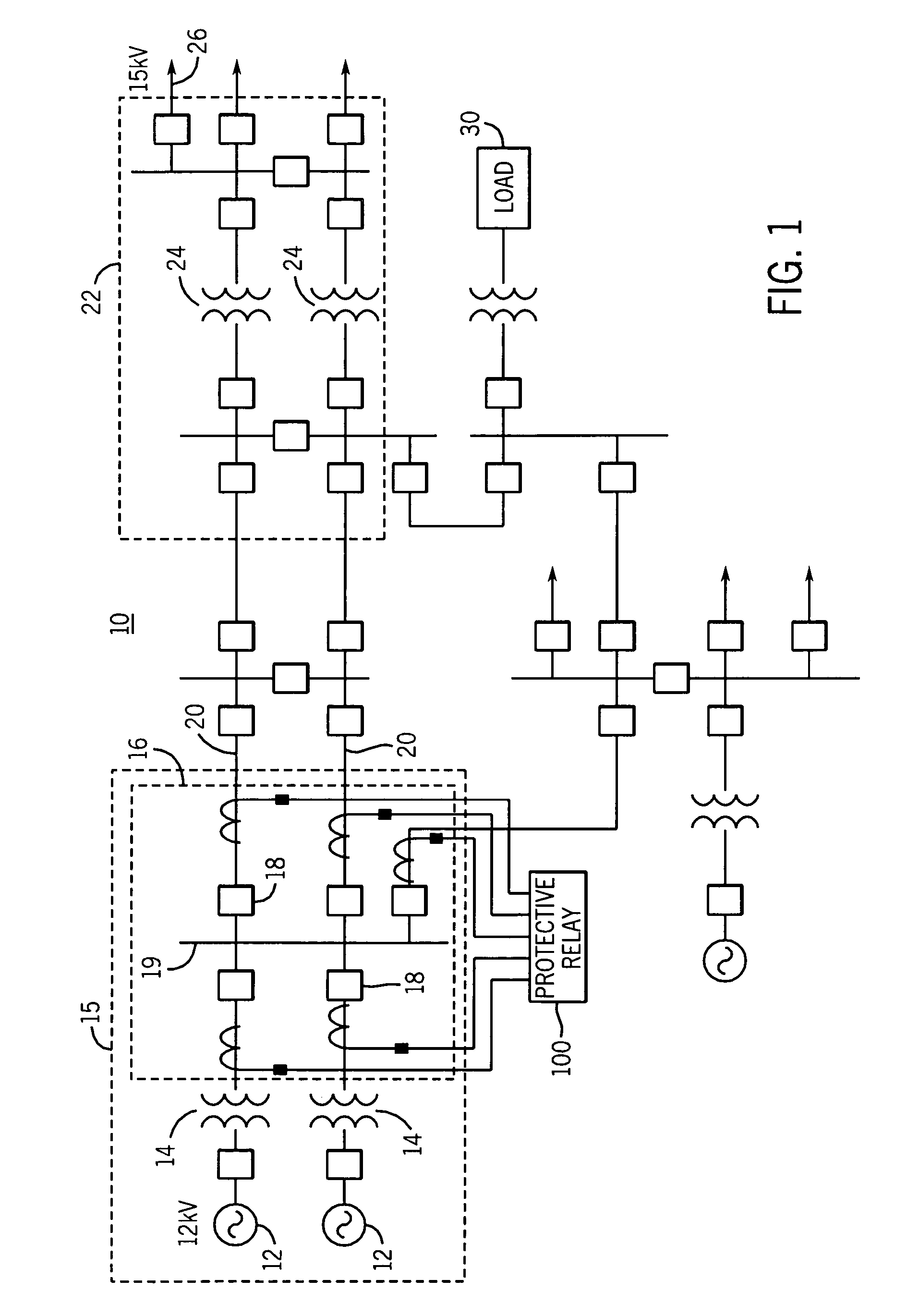
[0022]In addition to identifying an occurrence of a lost current transformer (CT) signal from among a number of CT signals, implementation of the apparatus and methods disclosed herein further enables identification of a specific lost CT signal provided by one of a number of CTs coupling a protective device to a protection zone of a three-phase power system. As a result, the associated CT responsible for the specific lost CT signal can be identified and steps may be taken to prevent protective device misoperation and to address the specific lost CT.

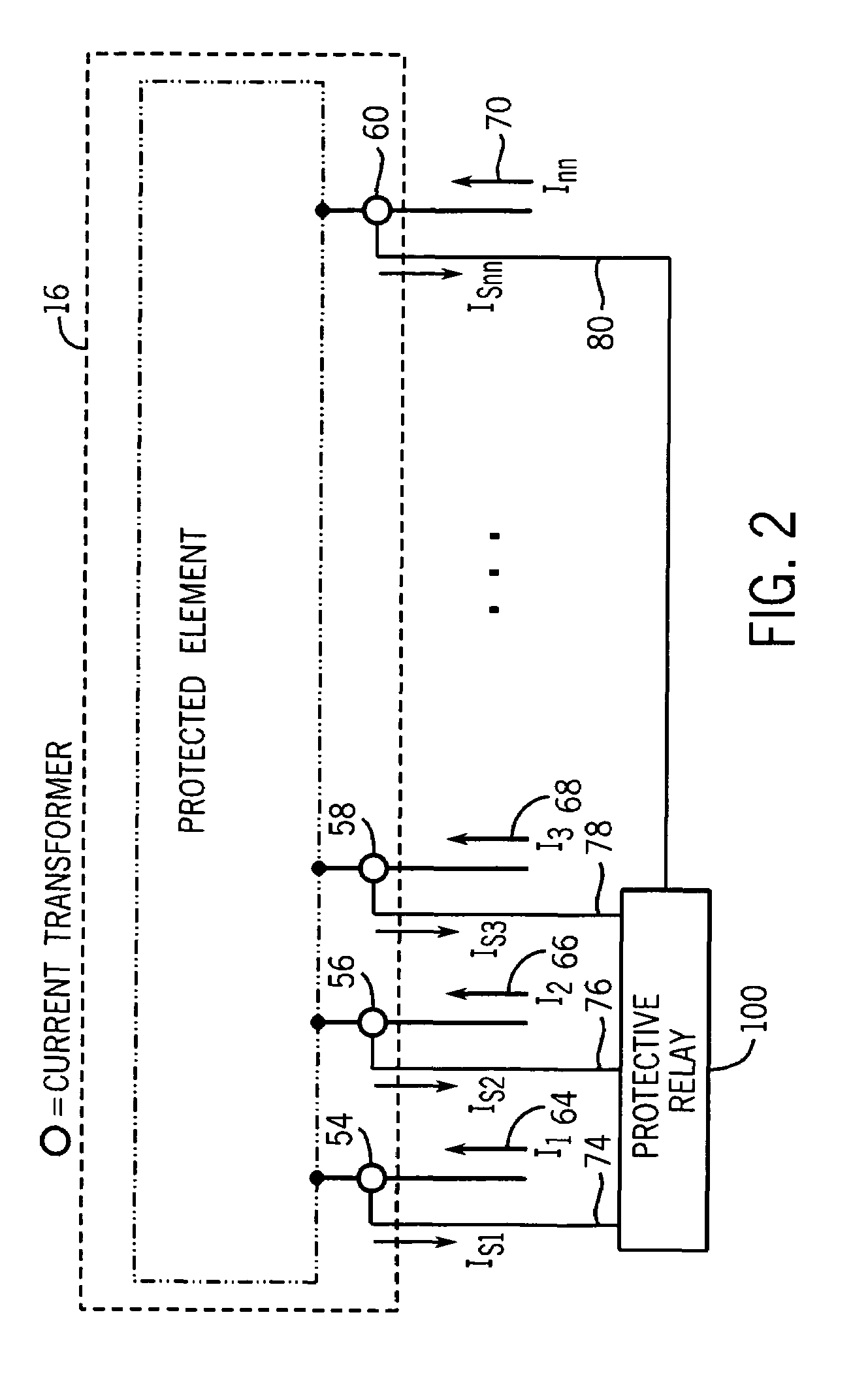
[0023]For ease of discussion, aspects of the present invention can be more fully understood by limiting the detailed discussion to a protection zone that is monitored by a protective relay, such as a current differential relay, coupled to the protection zone via a number nn of current transformers. Such a protection zone is defined herein to include a portion of a power system substation where only A-phase primary currents are monitored. ...


PUM


Abstract

Provided is an apparatus and method for identifying a specific lost current transformer (CT) signal of number of CT signals provided by a corresponding number of CTs coupling a protective device to at least one protection zone. The method includes selectively providing pairs of first and second binary control signals corresponding to each of the CT signals in response to comparisons of RMS current changes of respective CT signals. A third binary control signal associated with a protection zone is provided in response to receipt of the pairs of first and second binary control signals. A first value for only one of the first binary control signals, a second value for all of the second binary control signals and the first value for the third binary control signal for a predetermined time indicates the loss of the CT signal corresponding to the first binary control signal having the first value.

Description

CROSS-REFERENCE TO RELATED APPLICATIONS[0001]This application is related to U.S. Non-provisional patent application entitled “An Apparatus and Method for Detecting the Loss of a Current Transformer Connection Coupling a Current Differential Relay to an Element of a Power System”, filed on Mar. 2, 2005, naming Guzman-Casillas et al. as inventors.BACKGROUND OF THE INVENTION[0002]The present invention generally relates to power system protection, and more specifically, to an apparatus and method for identifying a loss of a current transformer signal in a power system.[0003]Electric utility systems or power systems are designed to generate, transmit and distribute electrical energy to loads. In order to accomplish this, power systems generally include a variety of power system elements such as electrical generators, electrical motors, power transformers, power transmission lines, buses and capacitors, to name a few. As a result, power systems must also include protective devices and pro...

Claims


Application Information

Patent Timeline
Patent Type & Authority Patents(United States)
IPC IPC(8): H02H7/00
CPCH02H1/0007H02H3/05
Inventor FISCHER, NORMANN
Owner SCHWEITZER ENGINEERING LABORATORIES
Why Eureka
Try Eureka