Rotatable bay window switch box surveillance camera and illuminator for facial recognition

a technology of facial recognition and surveillance camera, which is applied in the field of unobtrusive and covert surveillance cameras, can solve problems such as unsatisfactory video surveillan

Inactive Publication Date: 2008-03-18
BOSCH SECURITY SYST INC
View PDF13 Cites 52 Cited by
  • Summary
  • Abstract
  • Description
  • Claims
  • Application Information

AI Technical Summary

Benefits of technology

[0009]There may be lighting advantages as well as covert placement advantages in some situations to having a surveillance device illuminator contained in one such bay window switch box and a surveillance device camera contained in an adjacent or remotely located bay window switch box.

Problems solved by technology

Those camera placements often result in unsatisfactory video surveillance where the purpose is to obtain facial recognition of persons, due to the distance to the target area, and due to the position of the cameras taking only top head shots of target persons (who often wear hats).
It is also sometimes desirable to monitor a location with an unobtrusive or even hidden camera.

Method used


Image

  • Rotatable bay window switch box surveillance camera and illuminator for facial recognition
  • Rotatable bay window switch box surveillance camera and illuminator for facial recognition
  • Rotatable bay window switch box surveillance camera and illuminator for facial recognition

Examples


Embodiment Construction

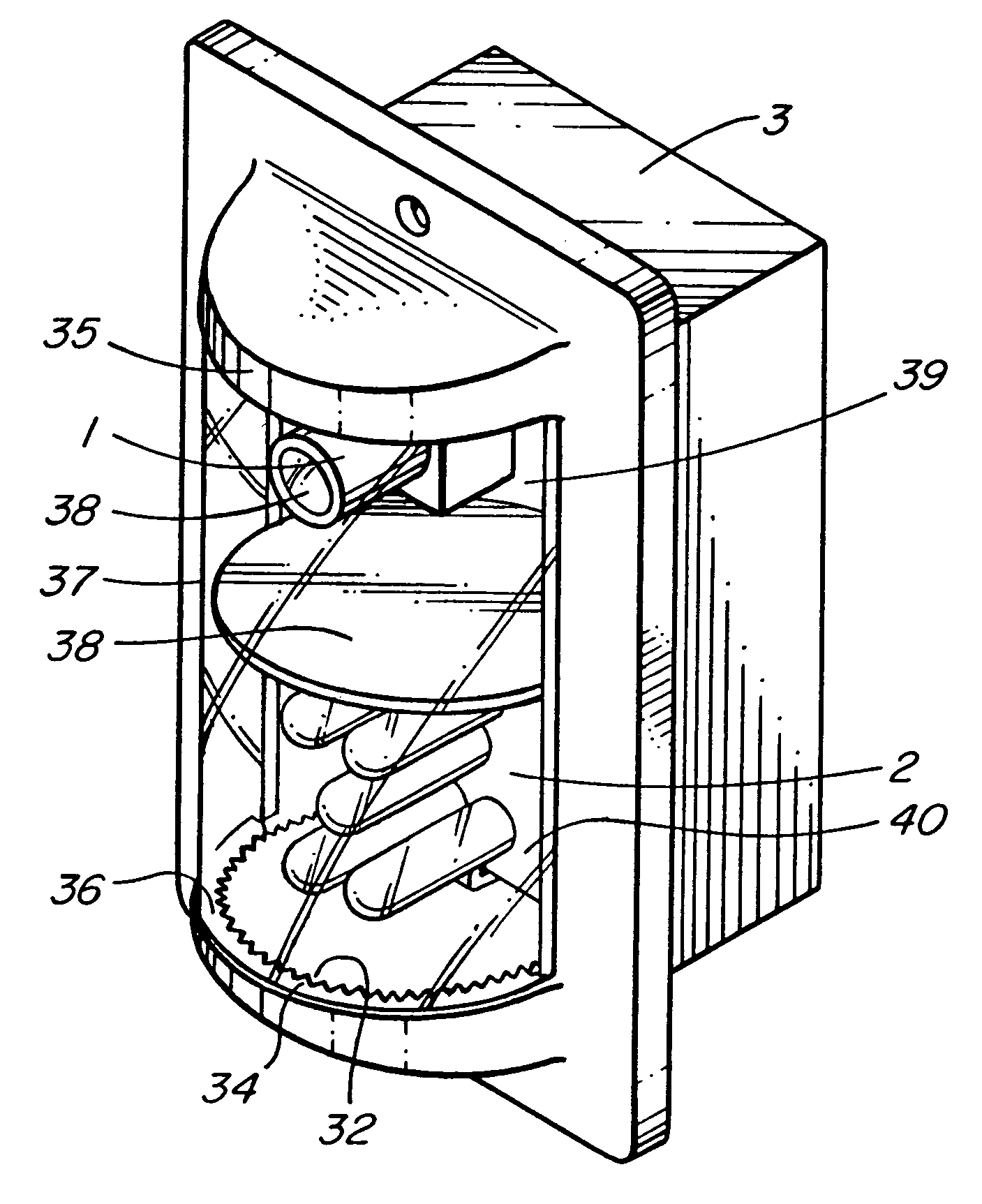
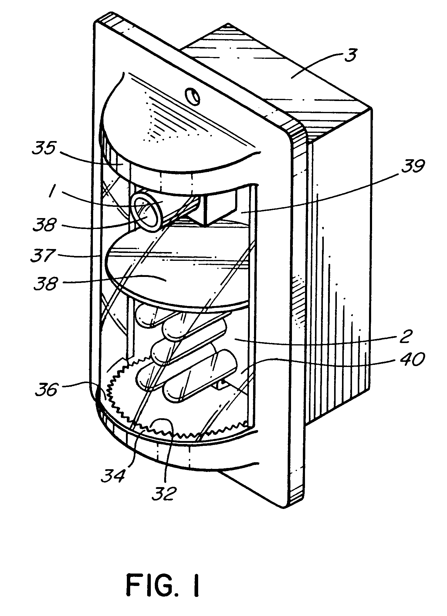
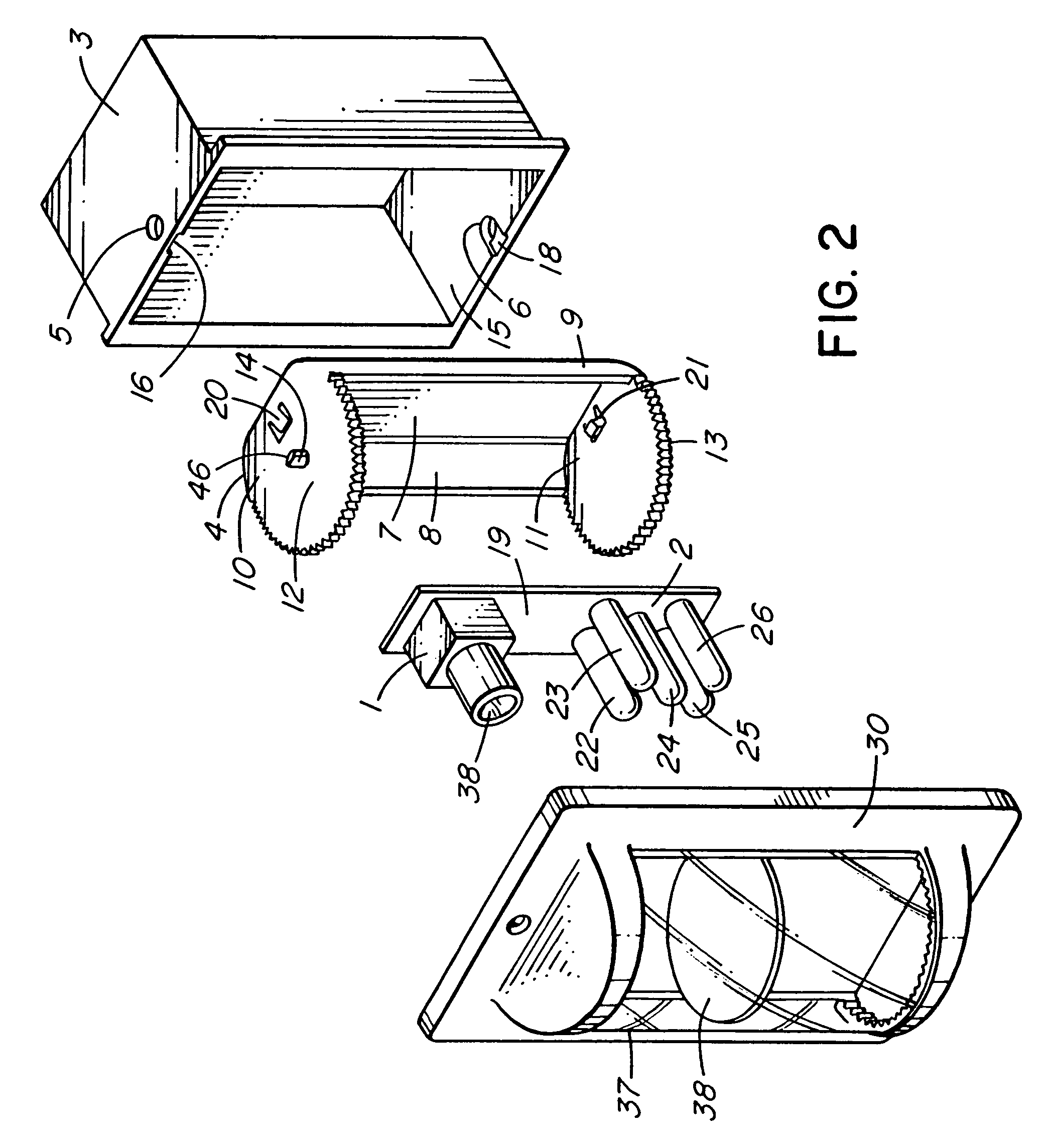
[0026]Referring to FIGS. 1 and 2, the camera 1 and the illuminator 2 are miniaturized such each could fit within half of a standard electrical switch box 3. A pair of pivot holes, with the top pivot hole shown at 5 and the bottom pivot hole shown at 6, are drilled in the top and bottom of the electrical switch box 3. A partially rotatable bay window inner frame 4 is provided. It has a back 7 and side portions 8 and 9 between the rear portions of each of its top 10 and its bottom 11, to make them rigid in the rear portions with respect to the back 7. It has a top front portion 12 and a bottom front portion 13, on each of which is formed a pivot pin (the top pivot pin being shown at 14) that can fit within the top pivot hole 5 and the bottom pivot hole 6 respectively, thereby allowing the bay window inner frame 4 to be partially rotatable within the front portion 15 of the electrical switch box 3. The pivot pin 14 has a sloped top, which allows it to slide readily along top guiding ch...


PUM


Abstract

A surveillance camera and illuminator are covertly mounted in a partially rotatable bay window inner frame mounted within an electrical switch box. The bay window inner frame can thus be pivoted back and forth to orient the camera toward an entrance to a room in which the switch box is mounted. When the bay window inner frame is rotated to the desired position, a bay window switch box decor cover plate is mounted over the bay window inner frame, engaging it and locking it in the selected position by attachment of the cover plate to the switch box.

Description

FIELD OF THE INVENTION[0001]This invention relates to unobtrusive and covert surveillance cameras.BACKGROUND OF THE INVENTION[0002]There exist miniaturized surveillance cameras which can record images in low light and no visible light conditions by means of infra-red illumination. It is common to mount surveillance cameras in a noticeable position, in order to deter illicit activity. But most such surveillance cameras are located high and away from human reach in order to minimize the risk of tampering. Those camera placements often result in unsatisfactory video surveillance where the purpose is to obtain facial recognition of persons, due to the distance to the target area, and due to the position of the cameras taking only top head shots of target persons (who often wear hats). Face shots are preferred and usually essential for identification of a person. It is also sometimes desirable to monitor a location with an unobtrusive or even hidden camera. By keeping the camera conceale...

Claims


Application Information

Patent Timeline
Patent Type & Authority Patents(United States)
IPC IPC(8): G06K9/00H04N5/225H04N7/18
CPCG06K9/00221H04N5/2252H04N5/2256H04N7/183G06V40/16H04N23/56H04N23/51
Inventor GIN, JACK
Owner BOSCH SECURITY SYST INC
Why Eureka
Try Eureka