
Re-terminable LC connector assembly and cam termination tool

a technology of lc connectors and connector assemblies, which is applied in the direction of optics, instruments, optical light guides, etc., can solve the problems of difficult and time-consuming endface polishing, high labor and expertise costs of standard “pot and finish” fiber optic connectors field installation, and the connections is well known for its more critical and difficult problems, so as to achieve simple and expedient field termination of fiber optic cables

Active Publication Date: 2008-03-18
PANDUIT
View PDF12 Cites 99 Cited by
  • Summary
  • Abstract
  • Description
  • Claims
  • Application Information

AI Technical Summary

Benefits of technology

The patent describes an improved fiber connector assembly that can be easily and positively terminated in the field using simple tools. The assembly allows for reversible termination, which means that if the termination is not acceptable, the fiber can be repositioned or replaced. The connector assembly also includes a cam tool that can be used to quickly and easily release the fiber connection. This tool can be hand-held or used with a support structure. The connector assembly is designed to allow for field testing of the connection and to improve the overall quality of fiber optic cables.

Problems solved by technology

However, compared to copper systems, fiber optic cables and connections are well known for their more critical and difficult termination.
Additionally, field installation of standard “pot and finish” fiber optic connectors is extremely labor and expertise intensive.
Endface polishing is difficult and time-consuming step, particularly when using single mode fiber, which achieves best performance when using an automated polishing machine.
However, automated polishing machines are often large and expensive, rendering them impractical for field use.
This eliminates much of the labor time, but requires the installer to purchase a fusion splicing machine and protective sleeve, which are also expensive.
However, the crimping operations, whether occurring at the interface point or at some other point to retain the field fiber, have a tendency to pull the field fiber and stub fiber apart, or otherwise damage the signal-passing function of the interface.
If the connection is found to be poor after the crimping occurs, the connector must be cut off because crimping is most often an irreversible operation.
This wastes both parts and labor, and can be an annoyance to a field installer by delaying installation.

Method used


Image

  • Re-terminable LC connector assembly and cam termination tool
  • Re-terminable LC connector assembly and cam termination tool
  • Re-terminable LC connector assembly and cam termination tool

Examples


Embodiment Construction

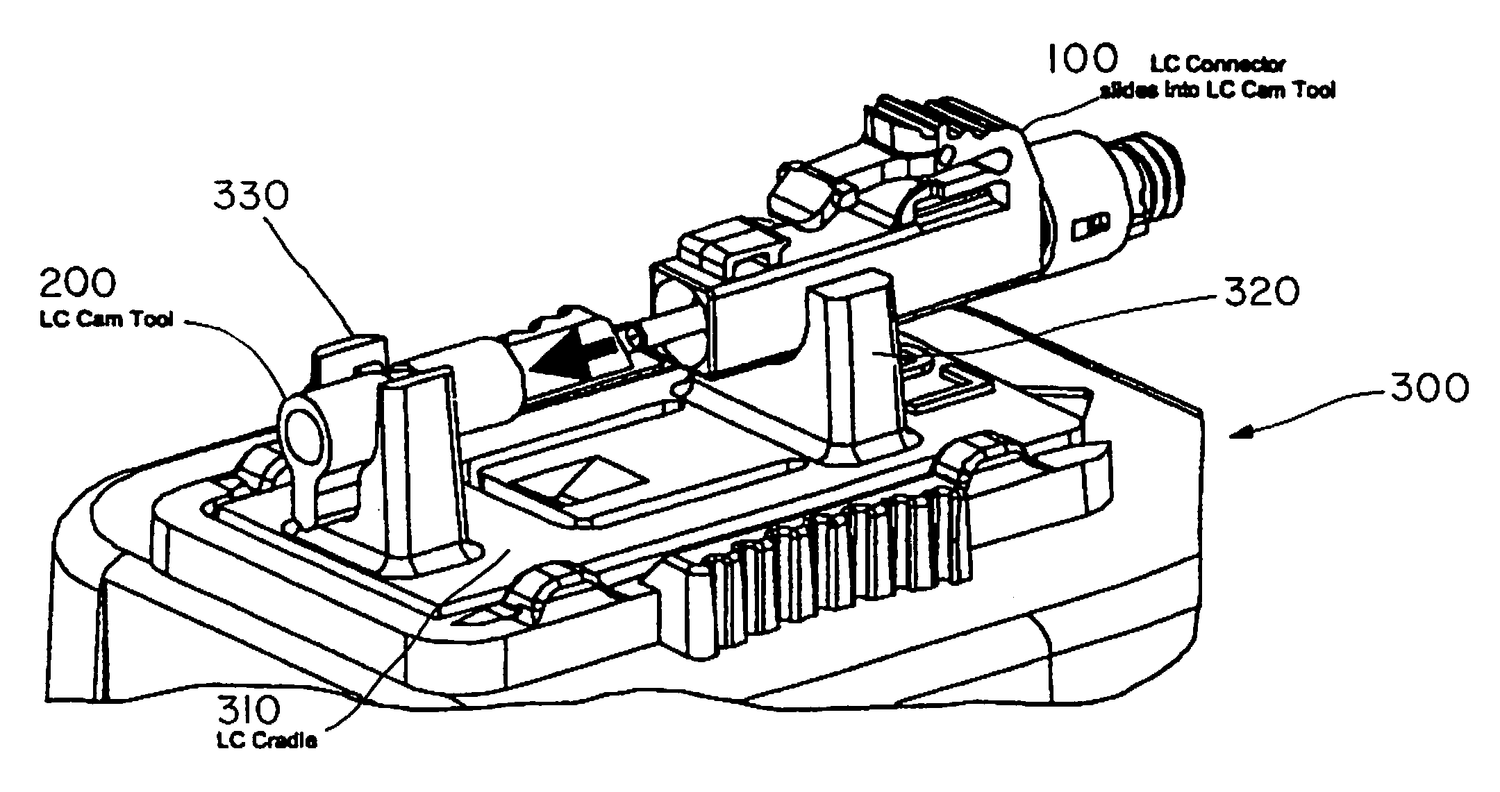
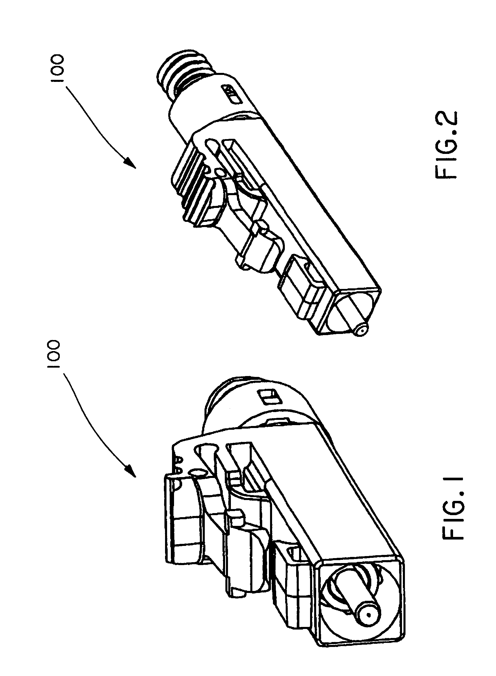
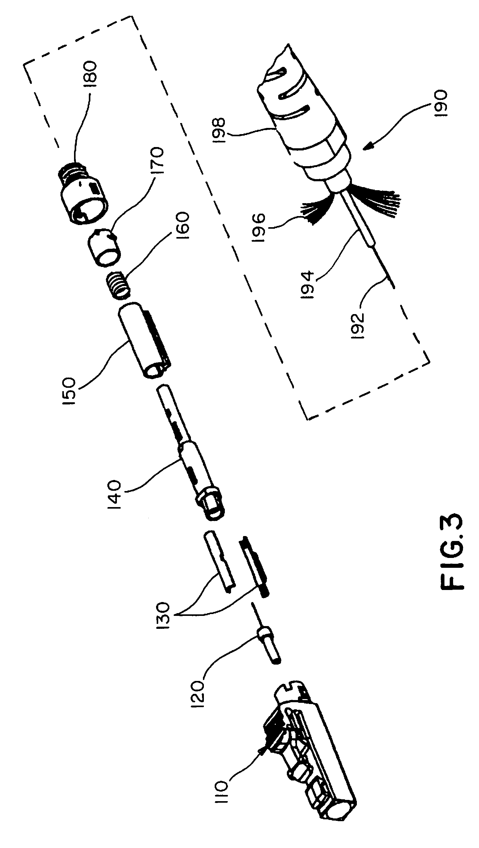
[0051]An exemplary embodiment of a re-terminable LC type fiber optic connector will be illustrated with reference to FIGS. 1-27. The fully assembled connector assembly 100 is shown in FIGS. 1-2 and an exploded view is shown in FIG. 3. LC connector assembly 100 includes an LC connector housing 110, stub ferrule assembly 120, planks 130, ferrule holder 140, cam sleeve 150, compression spring 160, cam detent 170, and backbone 180 that terminate a fiber optic cable 190. Cable 190 includes a field fiber 192, buffer 194, fibers 196, and outer body 198.

[0052]Additional details of each component of LC connector assembly 100 will be described with reference to FIGS. 4-15. FIGS. 4-5 illustrate front and rear views of connector housing 110. A front bore 111 allows access to ferrule holder 140 when using cam termination tool 200 (FIGS. 28-42). The rear bore includes a longitudinal keying groove 116 that mates with keying rib 156 (FIGS. 8-9) of cam sleeve 150 to maintain the cam sleeve orientati...


PUM


Abstract

An improved, reversibly terminable fiber stub connector assembly is provided that can be readily and positively terminated in the field using simple termination tools. This allows repositioning or replacement of fiber optic cable field fibers if termination is not acceptable in performance. The tool may be a hand-held tool, or used in conjunction with a connector support structure to provide simplified and expeditious field termination of fiber optic cables. The cam tool can include a throughbore that enables connection of a patchcord to the stub fiber of the connector during or shortly after termination without removal of the termination tool. Accordingly, field testing of the connection can be made at the site of termination.

Description

CROSS REFERENCE TO RELATED APPLICATION[0001]This application claims the benefit of U.S. Provisional Application No. 60 / 624,820 filed Nov. 4, 2004, and is incorporated herein by reference in its entirety.BACKGROUND OF THE INVENTION[0002]1. Field of Invention[0003]A re-terminable LC connector assembly includes a spring-loaded ferrule holder assembly and a reusable actuation system for termination of the assembly. An LC connector termination and cam tool enables ready assembly, termination and adjustment of the LC connector assembly.[0004]2. Description of Related Art[0005]Fiber optic networks are becoming increasingly commonplace in telecommunications applications due to their increased bandwidth and distance capabilities relative to copper networks. However, compared to copper systems, fiber optic cables and connections are well known for their more critical and difficult termination.[0006]Alignment between abutted glass cores within a fiber optic interface is crucial to the performa...

Claims


Application Information

Patent Timeline
Patent Type & Authority Patents(United States)
IPC IPC(8): G02B6/00
CPCG02B6/3802G02B6/3846G02B6/3858G02B6/3869G02B6/3877G02B6/3806G02B6/3898G02B6/3888
Inventor MARRS, SAMUEL M.WILTJER, JERRY A.BROUWER, SHAUN P.
Owner PANDUIT
Learn More