Reversible fiber optic connector

a fiber optic connector and reverse technology, applied in the field of reverse fiber optic connectors, can solve the problems of difficult end face polishing, high labor intensity and expertise in the field of standard “pot and finish” fiber optic connector installation, and the critical termination of fiber optic cables and connections, etc., to achieve the effect of ensuring positive termination and quick and positive termination

Active Publication Date: 2007-07-10
PANDUIT
View PDF14 Cites 127 Cited by
  • Summary
  • Abstract
  • Description
  • Claims
  • Application Information

AI Technical Summary

Benefits of technology

[0012]Advantageous features are a re-terminable fiber optic connector assembly having an internal cam mechanism that can terminate the fiber stub through relative rotation of at least one part of the connector assembly relative to another. The activation may be achieved using a hand-held cam activation tool, or used in conjunction with a connector support structure to provide simplified and expeditious field termination of fiber optic cables.
[0017]In accordance with yet additional aspects, because the cam is unexposed when mated, inadvertent de-activation can be prevented.

Problems solved by technology

However, compared to copper systems, fiber optic cables and connections are well known for their more critical and difficult termination.
Additionally, field installation of standard “pot and finish” fiber optic connectors is extremely labor and expertise intensive.
End face polishing is a difficult and time-consuming step, particularly when using single mode fiber, which achieves its best performance when using an automated polishing machine.
However, automated polishing machines are often large and expensive, rendering them impractical for field use.
However, these require a fusion splicing machine and protective sleeve, which are expensive.
However, the crimping operations, whether occurring at the interface point or some other point to retain the field fiber, have a tendency to pull the field fiber and stub fiber apart, or otherwise damage the signal passing function of the interface.
Moreover, if the connection is found to be poor after crimping, the connection must be cutoff because crimping is most often an irreversible operation.
Because of the small size of such re-terminable connectors, it is often difficult to terminate such connectors in the field.
Moreover, it was possible in prior designs for the connector to become accidentally de-activated during use.

Method used


Image

  • Reversible fiber optic connector
  • Reversible fiber optic connector
  • Reversible fiber optic connector

Examples


Embodiment Construction

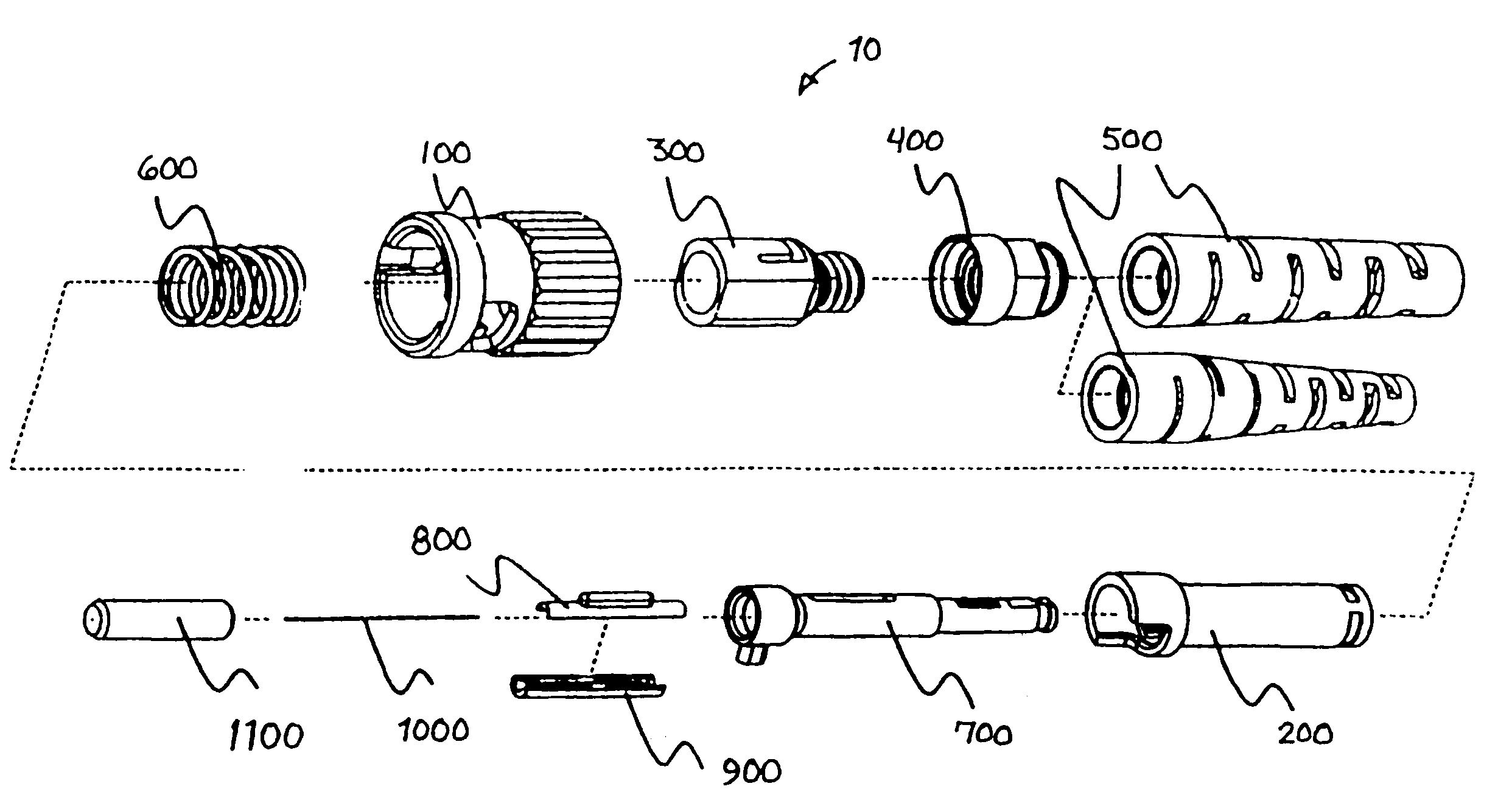
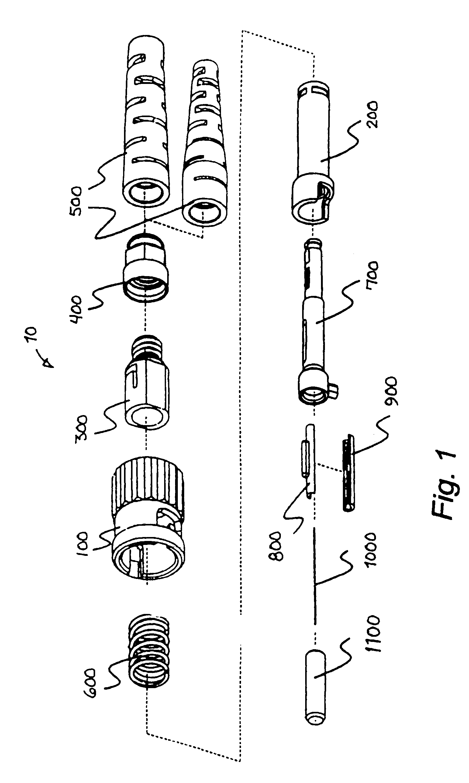
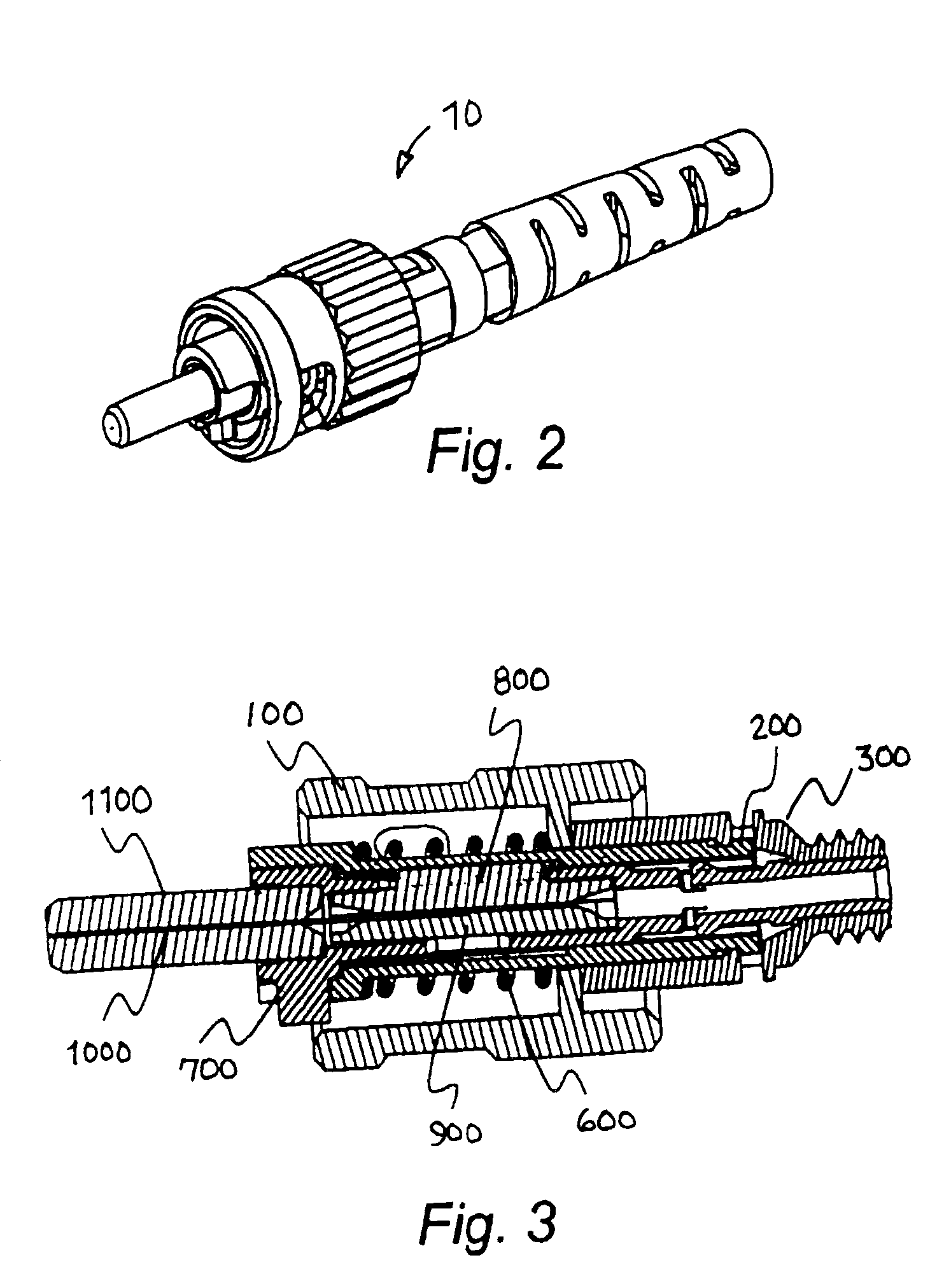
[0061]FIGS. 1–3 show an exemplary re-terminable fiber optic connector 10 in exploded, assembled and cross-sectional views. Connector 10 includes a bayonet 100, cam 200, backbone 300, retaining nut 400, strain relief boots 500, compression spring 600, ferrule holder 700, cam plank 800, Vee-plank 900, optical fiber stub 1000, and ferrule 1100. Connector 10 is designed to be terminated, for example, using either buffered optical fiber or jacketed optical fiber cable with an aramid fiber strength member. This particular exemplary optical connector is a no-crimp design in which rotation of cam 200 is used to activate or deactivate termination of the fiber in the connector. Rotation is preferably achieved using a cam activation tool, an example of which will be described later with reference to FIGS. 27–40.

[0062]Bayonet 100 provides a gripping surface for users while also retaining backbone 300 and spring 600. Bayonet 100 latches to a mating adapter (unshown) as known in the art. Cam 200 ...


PUM


Abstract

A re-terminable, no-crimp ST-type optical connector assembly includes a spring-loaded ferrule holder assembly and a reusable activation system for termination of the assembly. The optical connector can be terminated by a suitable cam activation tool. The connector includes a housing, such as a bayonet, matable to a mating adapter, a backbone retained within a rear of the housing, a ferrule holder provided within the backbone, and a cam provided between the ferrule holder and the backbone. The ferrule holder includes an alignment key exposed to mate with a cam activation tool to lock rotation of the ferrule holder relative to other connector components. The cam includes a cam activation cutout at a front face thereof that mates with a cam activation tool interface to enable rotation of the cam between de-activated and activated positions, the cam activation cutout also receiving the alignment key of the ferrule holder therethrough.

Description

BACKGROUND[0001]1. Field of Invention[0002]A re-terminable, no-crimp ST-type optical connector assembly includes a spring-loaded ferrule holder assembly and a reusable activation system for termination of the assembly. The optical connector can be terminated by a suitable cam activation tool.[0003]2. Description of Related Art[0004]Fiber optic networks are becoming increasingly commonplace in telecommunications applications due to their increased bandwidth and distance capabilities relative to copper networks. However, compared to copper systems, fiber optic cables and connections are well known for their more critical and difficult termination.[0005]Alignment between abutted glass cores within a fiber optic interface is crucial to the performance of the connection. Additionally, field installation of standard “pot and finish” fiber optic connectors is extremely labor and expertise intensive. In most applications, an installer is required to prepare a fiber end, glue the fiber end i...

Claims


Application Information

Patent Timeline
Patent Type & Authority Patents(United States)
IPC IPC(8): G02B6/38G02B6/36
CPCG02B6/3806G02B6/3846G02B6/3855G02B6/3826G02B6/3624G02B6/3802G02B6/3898G02B6/3887G02B6/3891G02B6/3888G02B6/38875
Inventor KUFFEL, GREGORY L.MARRS, SAMUEL M.BROUWER, SHAUN P.FITZPATRICK, ROBERT T.IRWIN, PHILLIP J.WAGNER, MATTHEW M.
Owner PANDUIT
Why Eureka
Try Eureka