Shaft seal having integrated removal feature

a technology of shaft seals and features, applied in the field of shaft seals, can solve the problems of difficult manufacturing of recessed steps, increased cost and complexity of seal manufacturing, and often thinner curling, and achieve the effect of minimizing parts and low cos

Inactive Publication Date: 2008-03-25
FEDERAL MOGUL WORLD WIDE LLC
View PDF21 Cites 19 Cited by
  • Summary
  • Abstract
  • Description
  • Claims
  • Application Information

AI Technical Summary

Benefits of technology

[0008]The invention has the advantage of providing a simple, low cost, robust solution to the removal of shaft seal assemblies. Incorporating the pull tabs into the inner casing minimizes parts and overcomes the shortcomings of the prior known solutions.

Problems solved by technology

Such a recessed step is difficult to manufacture consistently and the removal tool must be capable of exerting sufficient inward radial force in order to grip the recessed step with sufficient strength to enable the seal to be pulled from the bore.
This approach adds cost and complexity to the manufacture of seals.
However, the curl over is often thinner than the rest of the outer casing and is prone to tearing out under the extraction force of the tool or doesn't have sufficient length to allow easy removal.

Method used


Image

  • Shaft seal having integrated removal feature
  • Shaft seal having integrated removal feature
  • Shaft seal having integrated removal feature

Examples


Embodiment Construction

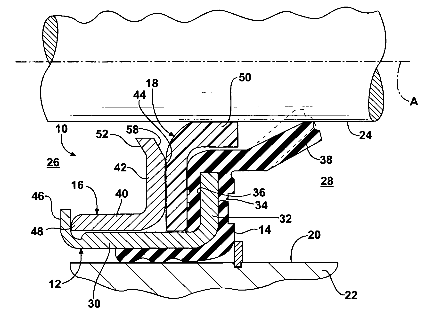
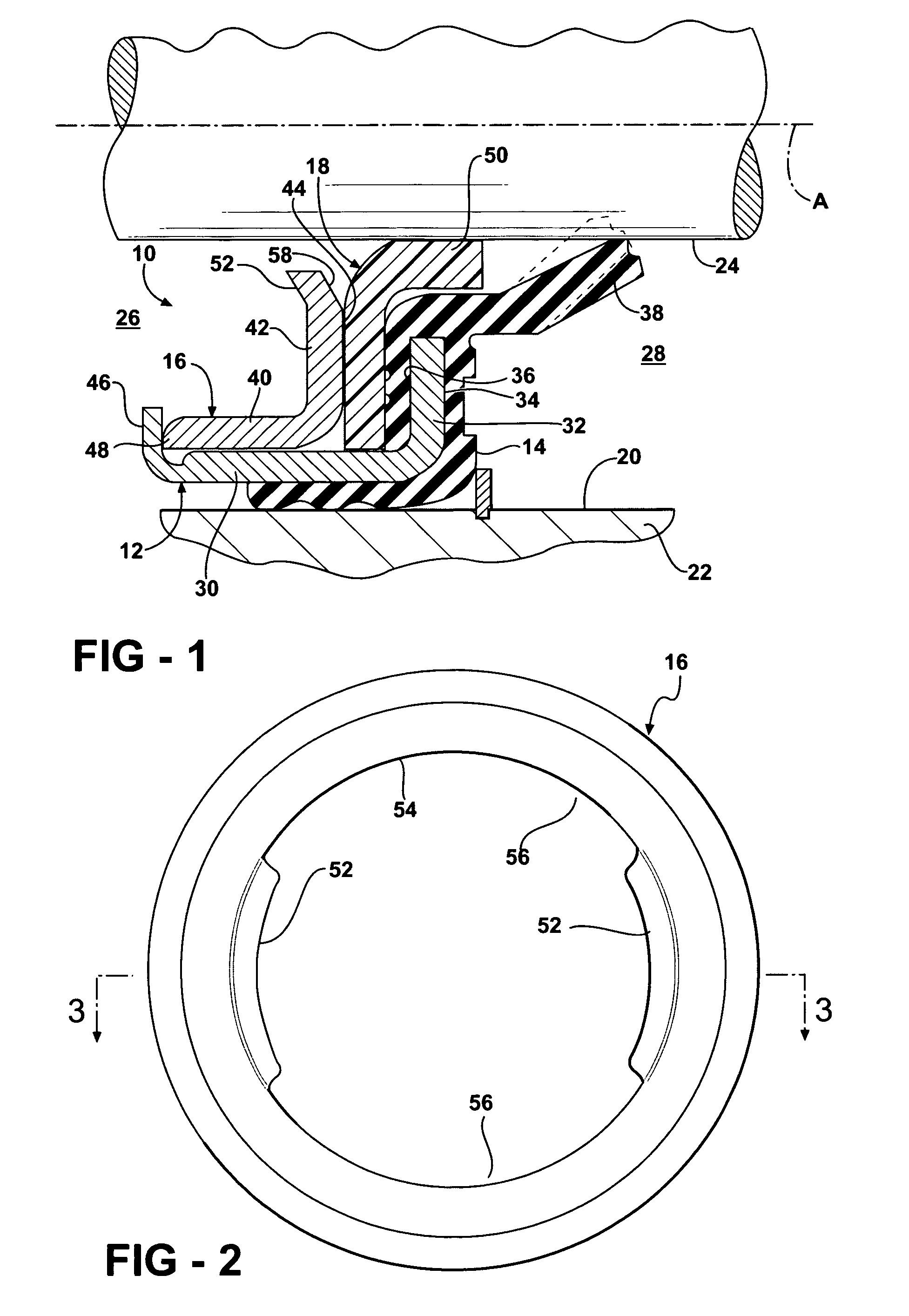
[0016]A dynamic shaft seal assembly constructed according to an embodiment of the invention is shown generally at 10 in FIG. 1 and includes an outer annular rigid support housing or metal case 12 having bonded thereto an elastomeric seal body 14, an inner annular rigid support housing or metal case 16, and a dynamic seal element 18 clamped between the inner and outer cases. As shown in FIG. 1, the case 16 is nested in the case 12. The seal assembly 10 is installable in a bore 20 of housing 22 to dynamically seal a rotatable shaft 24 extending through the bore 20. The seal assembly 10 has an air side 26 and an oil side 28 in relation to its orientation when installed in the bore 20. The seal assembly 10 operates to contain lubricant within the housing on the oil side 28 of the seal assembly 10 and to exclude contaminants from entering the housing 22 from the air side 26 of the seal assembly 10.

[0017]The outer case 12 includes an axially extending cylindrical mounting portion 30. An a...


PUM

PropertyMeasurementUnit
angleaaaaaaaaaa
acute angleaaaaaaaaaa
compressive loadaaaaaaaaaa

Abstract

A dynamic shaft seal assembly has inner and outer cases that are clamped together to secure a seal element therebetween for dynamic sealing about a rotatable shaft. The inner case is formed with integral pull tabs that are engageable by a seal removal tool to facilitate the removal of the seal assembly from a bore in which the seal assembly is installed.

Description

[0001]This application claims the benefit of U.S. Provisional Application No. 60 / 676,496, filed Apr. 29, 2005.BACKGROUND OF THE INVENTION[0002]1. Technical Field[0003]This invention relates generally to shaft seals, and more particularly to those having features that enable the seal to be removed from a bore after installation.[0004]2. Related Art[0005]Automotive air conditioning compressor seals that require removal for service rely on three know methods for providing a surface that can be engaged by a tool so that the seal can be removed once it is installed in a bore. One approach is to provide a recessed step in the outer casing of the seal. Such a recessed step is difficult to manufacture consistently and the removal tool must be capable of exerting sufficient inward radial force in order to grip the recessed step with sufficient strength to enable the seal to be pulled from the bore. Another approach is to add a separate pull ring component to the seal assembly. An example of ...

Claims


Application Information

Patent Timeline
Patent Type & Authority Patents(United States)
IPC IPC(8): F16J15/32
CPCF16J15/3268Y10T29/49719F16J15/32
Inventor MADIGAN, CHRISTOPHER
Owner FEDERAL MOGUL WORLD WIDE LLC
Why Eureka
Try Eureka