Focusable spotlight with asymmetrical light distribution

a spotlight and asymmetric technology, applied in the field of spotlights, can solve the problems of unfocusable, unfavorable light distribution results, unfavorable adjustment of light distribution results, etc., and achieve the effect of reducing energy expenditure, facilitating light intensity transition, and facilitating lighting

Inactive Publication Date: 2008-03-25
DEDO WEIGERT FILM
View PDF11 Cites 4 Cited by
  • Summary
  • Abstract
  • Description
  • Claims
  • Application Information

AI Technical Summary

Benefits of technology

[0008]It is the particular advantage of the spotlight of the present invention to combine the deliberate asymmetry in the light distribution with the focusability of the spotlight, which results in extraordinarily flexible application possibilities, even where one single spotlight is concerned. In the above-mentioned application in a museum and the replacement of the large picture with the small one, for example, a spotlight of the present invention does not need to be replaced during the exchange of these pictures. It merely needs to be focused on the new picture size, that is, its angle of radiation must be adjusted to the new picture size. The spotlight itself, however, can remain in its present spatial position and does not need to be replaced by a totally different spotlight.
[0009]Furthermore, the spotlight of the present invention provides a continuous, even light intensity transition. Thus, the total intensity of the available light can be fully utilized. Consequently, lower wattages can be used and the corresponding energy loss can be minimized. With all indoor applications, the accumulation of heat is thereby also reduced accordingly. This is of particular advantage considering that to this day, incandescent spotlights are still most frequently used for indoor applications and in studios, whereby the actual usable light is only about 10% of the expended energy.
[0012]This method of illumination, whereby the intensity of the light that is directed towards the camera oftentimes is twice as much as that of the incident light from the camera side, will never be quite obsolete so that the focused light will still play an essential part, even with a very uniform, soft general illumination. Primarily in a case when the objects move while a picture is taken, the asymmetrical illumination with light that is focused by the focusable spotlights of the present invention offers substantial advantages, namely softer light intensity transitions and the reduced energy expenditure.
[0013]Most often, a focusable spotlight is positioned as a focused light at an angle of about 45 degrees radiating downward, whereby at the same time one can go by the assumption that the focused light is practically never employed directly from the camera axis but also at an angle, which laterally can frequently be 45 degrees, whereby greater angle variations can occur, which essentially can be compensated for by rotatably orienting the front lens. In addition, angle variations can be adjusted by the slideability of the eccentric front lens. With this embodiment of the spotlight of the present invention, it is possible to change the radial distance between the principal optical axis of the front lens and the principal optical axis of the spotlight.

Problems solved by technology

However, all of these conventional asymmetrical floodlights or foot ramps are always open-face lights without a front lens.
They are also not focusable.
Per the state of the art, if in a museum, for example, a large picture is replaced with a smaller one, a new asymmetrical floodlight, suitable to illuminate the smaller picture, must be mounted because it is not possible to focus the original floodlight, which was proper for the large picture, on the smaller surface.
Furthermore, unfavorable light distribution results have been adjusted, in many cases, with half scrims, according to the state of the art.
However, a truly perfect transition is thereby not accomplished, only a half-surface shading, that is, reduction, of the light intensity.
However, a continuous, even light intensity transition is not provided by the conventional half scrims.

Method used


Image

  • Focusable spotlight with asymmetrical light distribution
  • Focusable spotlight with asymmetrical light distribution
  • Focusable spotlight with asymmetrical light distribution

Examples


Embodiment Construction

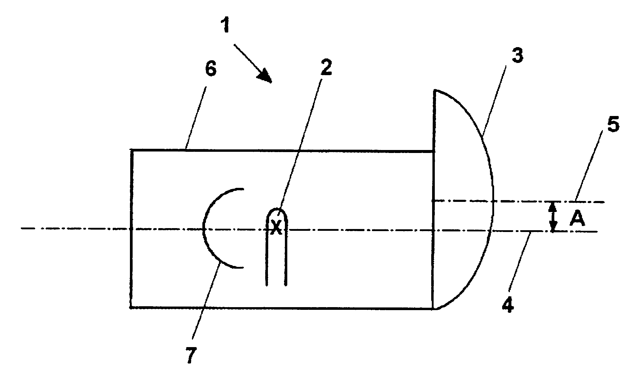
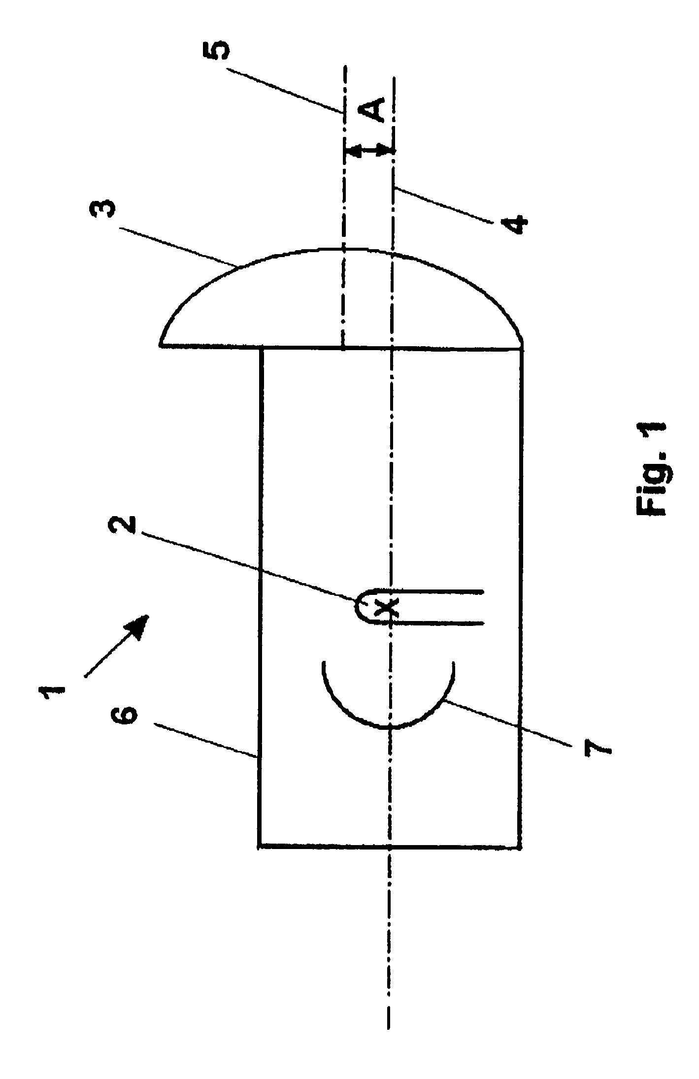
[0021]Reference will now be made in detail to the preferred embodiment of the present invention, examples of which are illustrated in the accompanying drawings. Wherever possible, the same reference numbers will be used throughout the drawings to refer to the same or like parts. Hereinafter, embodiments of the present invention will be explained with reference to FIGS. 1 through 5.

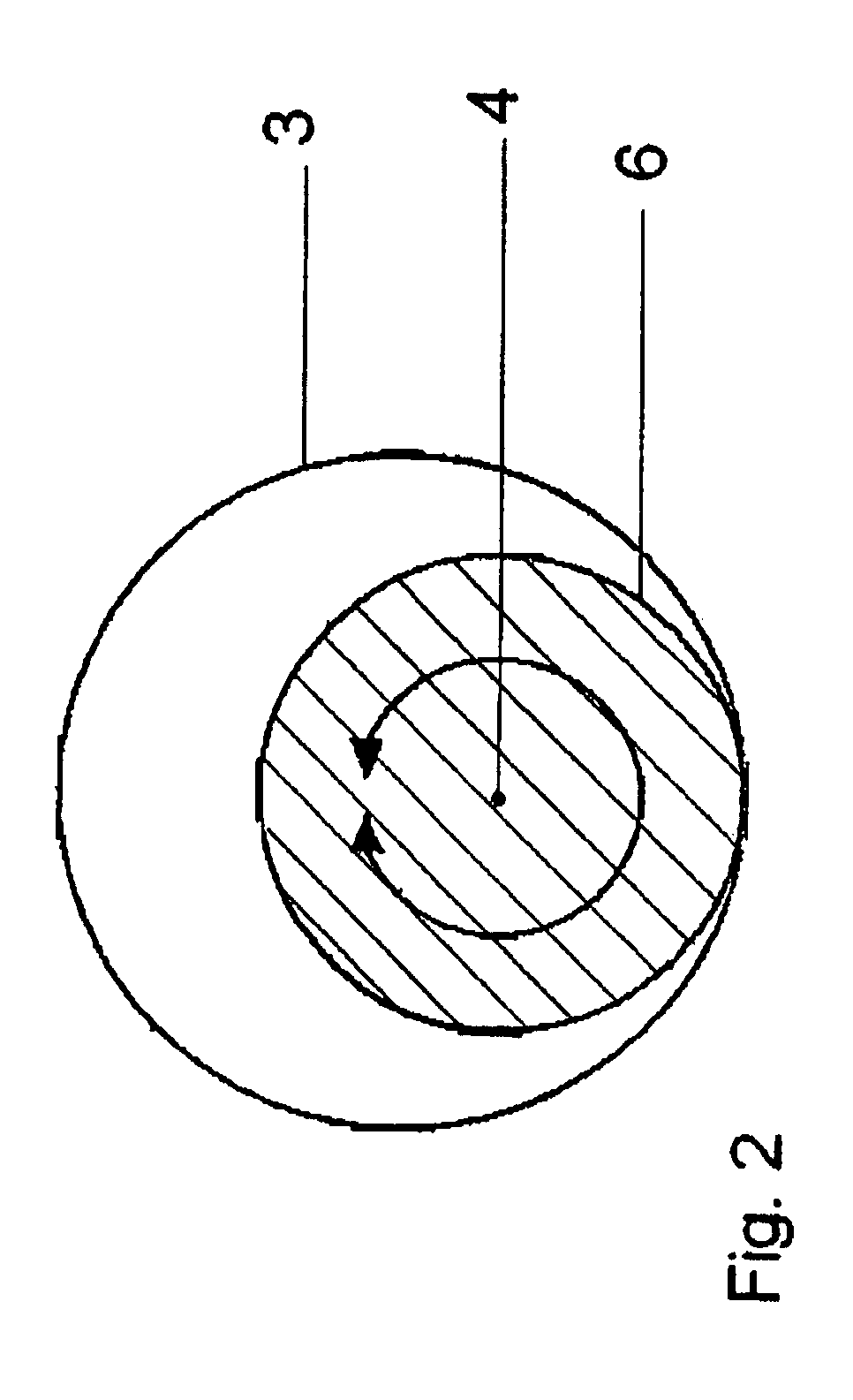
[0022]A spotlight 1, which is illustrated in FIG. 1 as a first embodiment of the invention, comprises a housing 6. Inside the housing 6, a lamp 2 and a reflector 7 assigned to lamp 2, are arranged. A principal optical axis 4 of the spotlight 1 extends through the lamp 2 and the reflector 7 in the center of the cavity formed by the housing 6, as shown in FIG. 1.

[0023]The lamp 2 and the reflector 7 are movable inside the spotlight 1 so that the angle of radiation of the spotlight 1 can be altered. The ability to alter the angle of radiation is known from prior art and will not be described herein. For exampl...


PUM


Abstract

A spotlight having a variable angle of radiation includes a light source and a converging lens. The converging lens is the front lens of the spotlight. The front lens is eccentrically arranged such that the principal optical axis of the front lens is not coincident with the principal optical axis of the spotlight. For example, the principal optical axis of the front lens is parallel to and spaced from the principal optical axis of the spotlight by a predetermined distance.

Description

BACKGROUND OF THE INVENTION[0001]1. Field of the Invention[0002]The invention is directed to a spotlight having a variable angle of radiation.[0003]2. Description of the Related Art[0004]Spotlights having variable angles of radiation are known, for example, from Applicant's prior patents such as U.S. Pat. No. 4,823,243, U.S. Pat. No. 6,004,007, U.S. Pat. No. 6,499,862, and U.S. Pat. No. 6,575,598. The object of the above-listed exemplary spotlights is in the technical design, wherein the emitted light intensity is as even as possible in any radiation angle position of the spotlight. With certain spotlight applications in the fields of film, television, photography, and museums, an evenly emitted light intensity is not advantageous. For example, with an application in a museum, one can normally assume that the spotlight is mounted higher than the object to be illuminated, whereby in an extreme case, the upper rim of the object is only half the distance away from the light source than...

Claims


Application Information

Patent Timeline
Patent Type & Authority Patents(United States)
IPC IPC(8): F21V17/02F21S8/00F21V1/00F21V5/04F21V14/06
CPCF21S8/00F21V5/04F21V14/06F21W2131/406
Inventor WEIGERT, DEDO
Owner DEDO WEIGERT FILM
Why Eureka
Try Eureka