Power interface with LEDs for a TRIAC dimmer

Active Publication Date: 2014-03-25
KONINK PHILIPS ELECTRONICS NV
View PDF12 Cites 2 Cited by
  • Summary
  • Abstract
  • Description
  • Claims
  • Application Information

AI Technical Summary

Benefits of technology

[0006]It is an object of the present invention to overcome this problem, and to provide a power interface which keeps an adjustable power supply circuit in a conducting state even if the average current consumption of an attached load is below the adjustable power supply circuit's holding current requirement.
[0010]Thus, one advantage of the power interface is that it is arranged to operate a load, such as a light source, from an adjustable power supply circuit, such as a standard wall dimmer, below the adjustable power supply circuit's original minimum load requirements. A further advantage is that the power interface is arranged to operate a load from an adjustable power supply circuit even below the adjustable power supply circuit's minimum holding current.
[0014]The current shaper may be activated during a time duration of the period that is long enough to ensure that the adjustable power supply is in a conducting state. The time duration of the activation typically depends on the period of the current shaper, as a longer period of low current will require a longer period of higher current to keep the adjustable power supply in a conducting state. With proper control of the period and the activation time, improved operation can be achieved. Alternatively, more than two time intervals and more than two current levels can be defined and applied, so as to have a special waveform to improve operation with certain adjustable power supply circuits.
[0016]The boost converter may be configured for a fixed peak current, in order to facilitate circuit design. In other words, this can reduce the complexity of the control loop of the current shaper.
[0020]One advantage may be that the power interface may enable TRIAC-dimmed LED light sources at low wattages.

Problems solved by technology

However, due to the recovery time of the adjustable power supply circuit, it will in fact stay in the conducting state even if there is no current flowing for a short period of time.

Method used


Image

  • Power interface with LEDs for a TRIAC dimmer
  • Power interface with LEDs for a TRIAC dimmer
  • Power interface with LEDs for a TRIAC dimmer

Examples


Embodiment Construction

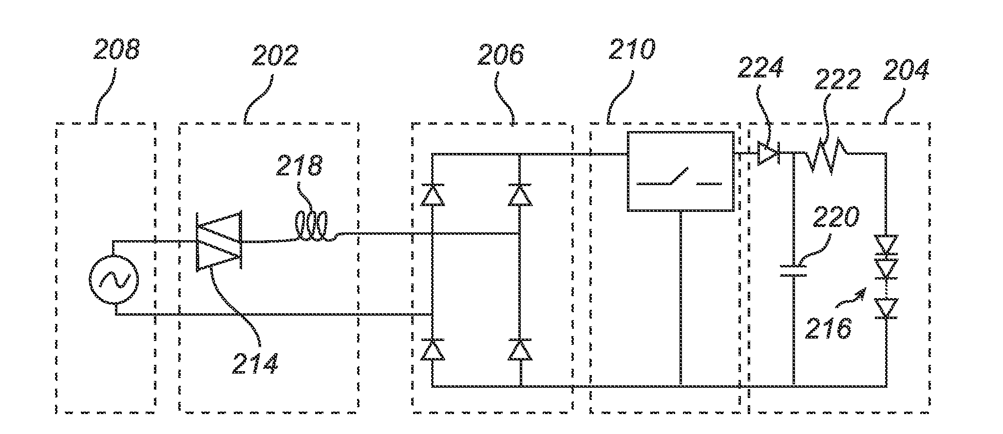
[0029]The embodiments below are provided by way of example, so that this disclosure will be thorough and complete, and fully conveys the scope of the invention to those skilled in the art. Like numbers refer to like elements throughout. The examples relate to a general power interface for connecting a load to an adjustable power supply circuit having a time-dependent holding current level. In the examples below the adjustable power supply circuit is sometimes embodied as a TRIAC which may be part of a dimmer. However, the adjustable power supply circuit may be any adjustable power supply circuit fulfilling any requirements set forth below. In the examples below the load is sometimes embodied as a (LED-based) light source. However, the load may be any suitable load fulfilling any requirements set forth below.

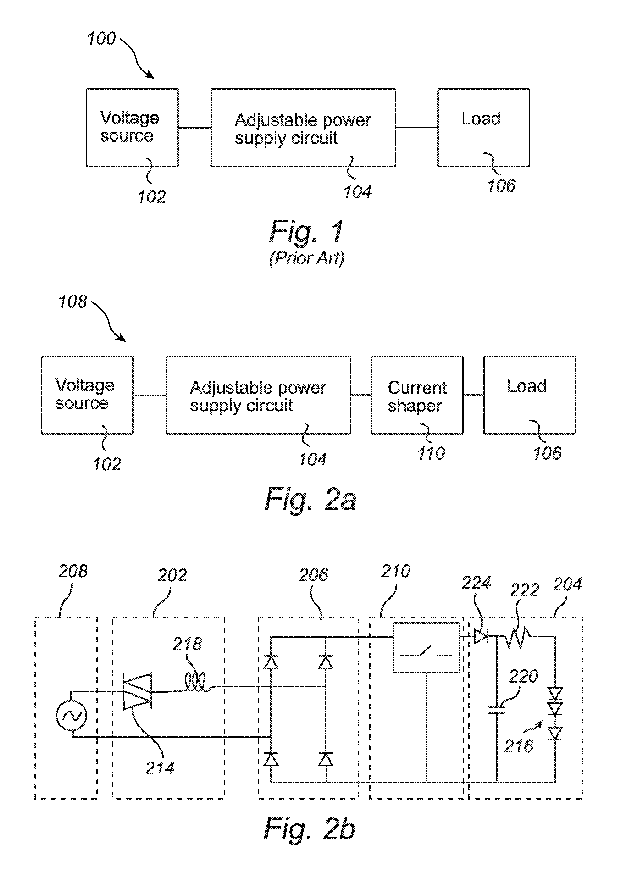
[0030]FIG. 1 illustrates a prior art circuit 100 comprising a voltage source 102, an adjustable power supply circuit 104 and a load 106. The adjustable power supply circuit may h...


PUM


Abstract

A power interface is proposed, which keeps an adjustable power supply circuit in a conducting state even if the average current consumption of an attached load is below the adjustable power supply circuit's holding current requirement. The power interface makes use of the dynamic properties of adjustable power supply circuits. Due to the recovery time of the adjustable power supply circuit, it will stay in the conducting state even if there is no current flowing for a short while. The power interface makes use of this effect by interrupting and re-establishing a current flow from the adjustable power supply circuit.

Description

FIELD OF THE INVENTION[0001]The present invention relates to a power interface. Particularly it relates to a power interface for connecting a load to an adjustable power supply circuit having a time-dependent holding current level or other restrictions on the load current.BACKGROUND OF THE INVENTION[0002]For a high market penetration of solid state light sources, such as Light Emitting Diode (LED) light sources, at the time being, retrofit lamps are considered quite important. For most consumer luminaires the user / customer may be able to replace only the sole light source (e.g. the incandescent light bulb) inside a luminaire with a modern LED light source at low initial cost. Not only the compatibility with the socket but also the compatibility with the existing installation / circuitry is quite important. Therefore, the light source should fit into existing sockets and should be compatible with the existing electrical installation, including dimmers. This includes interoperability wi...

Claims


Application Information

Patent Timeline
Patent Type & Authority Patents(United States)
IPC IPC(8): H05B37/02G05F3/02H05B44/00
CPCY02B20/383H05B33/0824H05B33/0815H05B45/44Y02B20/30H05B45/38H05B45/37
Inventor RADERMACHER, HARALD, JOSEF, GUNTHER
Owner KONINK PHILIPS ELECTRONICS NV
Why Eureka
Try Eureka