Meter socket assembly

a technology of meter sockets and sockets, applied in the direction of coupling contact members, coupling device connections, instruments, etc., can solve the problems of springs not providing consistent pressure, spring bias force may exceed the industry standard limit, and shape limits the thickness of materials used, so as to achieve the effect of maximizing the contact of the meter blad

Active Publication Date: 2008-03-25
SIEMENS ENERGY & AUTOMATION INC
View PDF17 Cites 16 Cited by
  • Summary
  • Abstract
  • Description
  • Claims
  • Application Information

AI Technical Summary

Benefits of technology

[0012]It is a further object of this invention to provide a meter jaw that will guarantee electrical connection even if there is misalignment between the meter jaw and the meter blade.
[0013]It is further object of this invention to provide a jaw spring guide with side arm guides to hold a meter blade in position and help guide the meter blade vertically into the meter socket and maximize contact of the meter blade between the bus bar and meter jaw.

Problems solved by technology

One disadvantage of the current meter socket is that the spring bias force may exceed the industry standard limit for the force required to insert and extract the watt-hour meter.
Another disadvantage of the current meter socket is that the spring does not provide consistent pressure over time for a reliable connection between the meter jaw and watt-hour meter blade.
A disadvantage of the one-piece jaw, is that its shape limits the thickness of material used and more importantly, the one-piece jaw provides a long electrical current path by not directly contacting the meter blade and the bus bar.
Similarly, there is a large amount of heat generated at the point of conduction in both the one piece and two piece jaws where such heat rise may cause meter malfunction if not properly dissipated.
Another disadvantage of the known meter socket is the difficulty in aligning both the one piece and the two piece jaws in both the vertical and horizontal direction with the meter blade.

Method used


Image

  • Meter socket assembly
  • Meter socket assembly
  • Meter socket assembly

Examples


Embodiment Construction

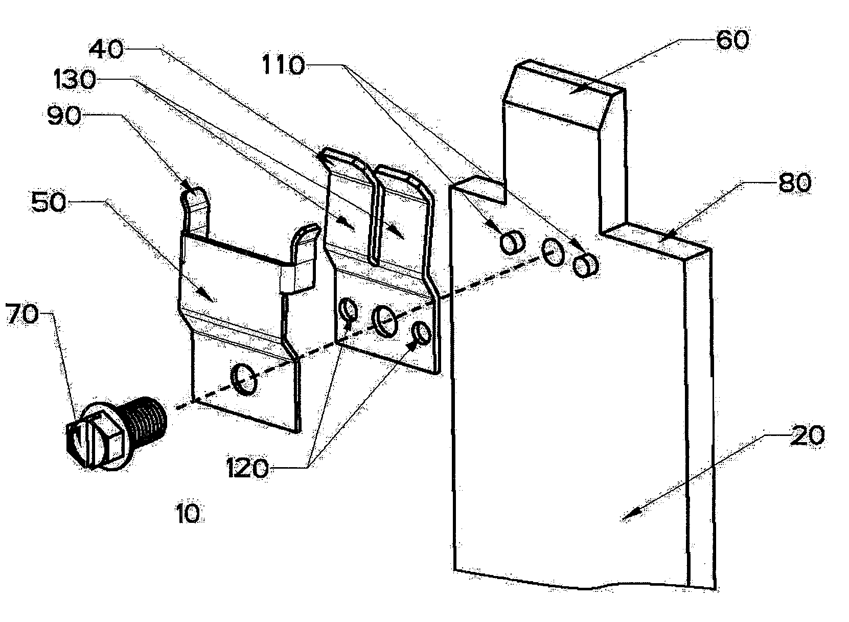
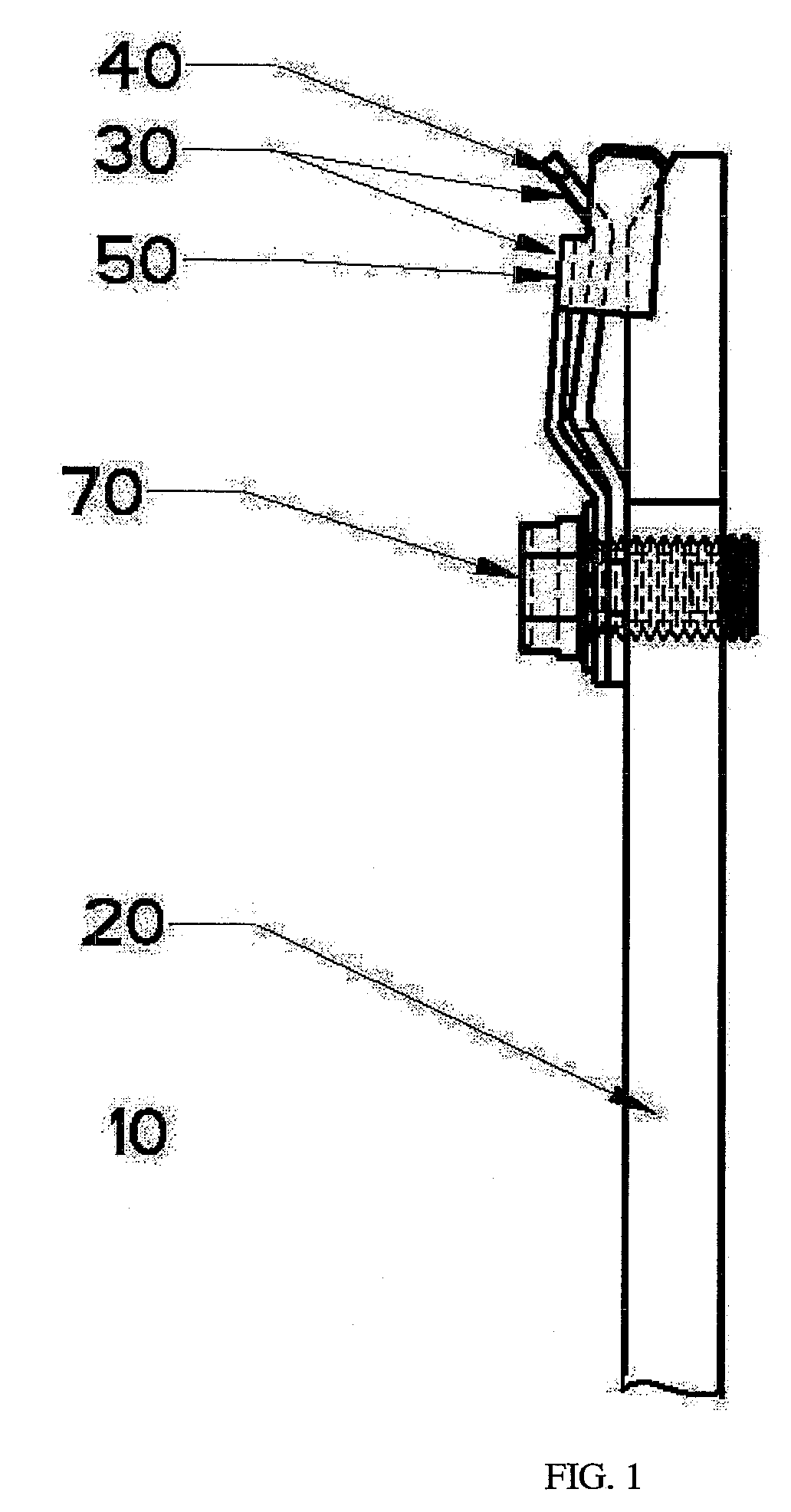
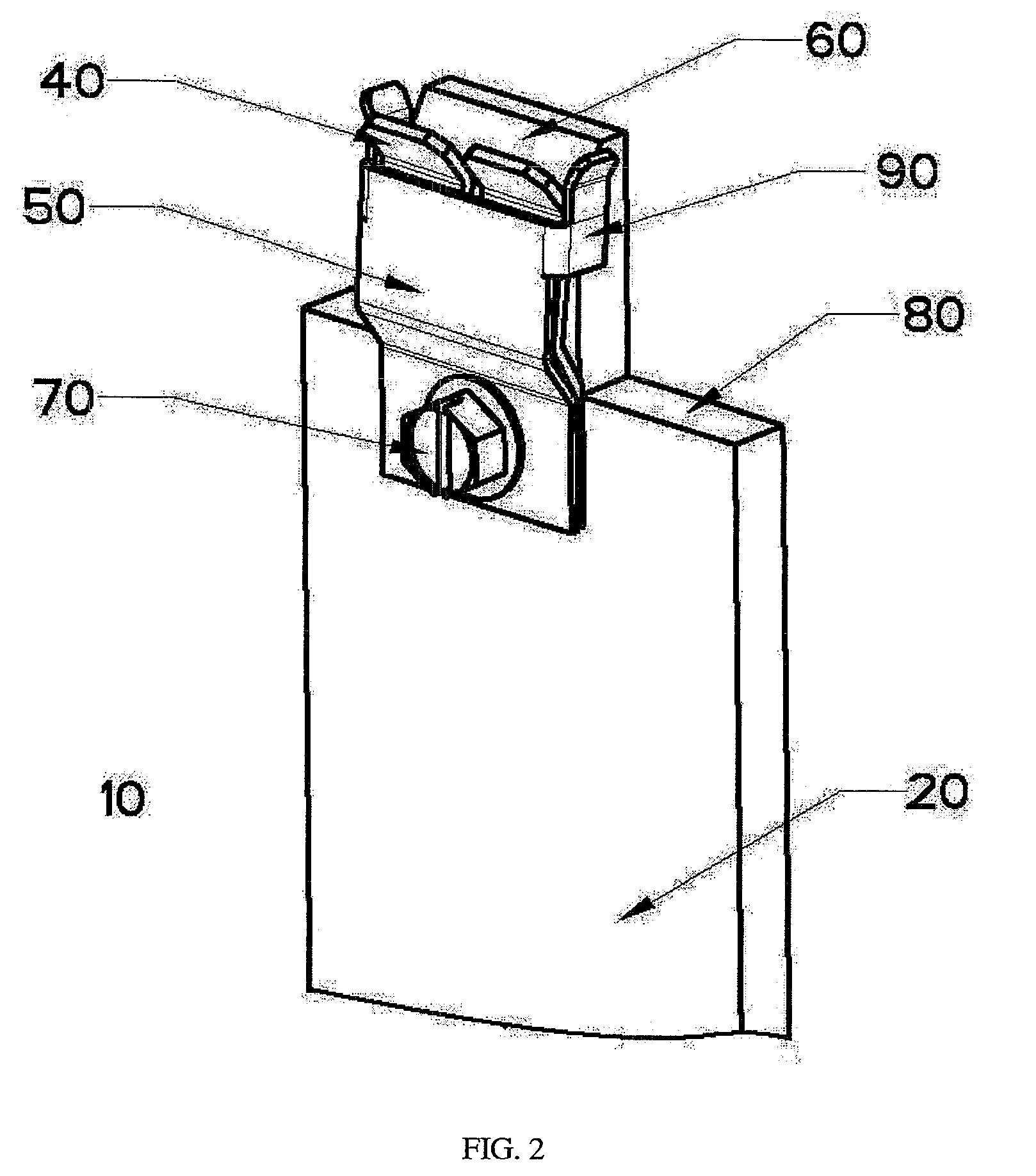
[0025]Referring to FIG. 1, meter socket assembly 10 includes an extended bus bar 20 and a meter jaw assembly 30. Meter jaw assembly 30 comprises a meter jaw 40 and jaw spring guide 50 that overlies meter jaw 40. The extended bus bar 20 features a chamfered receptacle terminal 60 (see FIG. 2) that is coupled with meter jaw 40. Chamfered receptacle terminal 60 creates a “V” shaped receptacle terminal with the upper portion of meter jaw 40 for easily inserting a meter blade (not shown) from a watt hour meter into the meter socket assembly 10. The upper portion of the meter jaw 40 has an outward bend away from the chamfered receptacle terminal 60. The middle portion of the meter jaw 40 has an outward joggle bend which then leans inward towards the extended bus bar 20. The outward joggle bend shape helps meter jaw 40 fully contact the meter blade under load and also provides a bias spring force to press the meter blade to extended bus bar 20. Extended bus bar 20 acts not only as a conduc...


PUM


Abstract

A meter socket assembly comprising a meter jaw assembly and an extended bus bar for contact with a meter blade of a watt hour meter. The meter jaw assembly further comprises a meter jaw and a jaw spring guide that are mounted together by a fastening device to the extended bus bar. The extended bus bar comprises a chamfered terminal end and cutout portion to easily accept the meter blade. The jaw spring guide overlies the meter jaw and applies a bias force inward to urge the contact face of the meter jaw toward the extended bus bar closing any insertion space and guaranteeing tight contact with the meter blade. A meter socket guide snaps on to the bus bar to maintain the alignment of meter jaw with watt-hour meter blade.

Description

CROSS REFERENCE OF RELATED APPLICATION[0001]This application claims priority to and incorporates by reference herein in its entirety, pending U.S. Provisional Patent Application Ser. No. 60 / 717,802 filed on Sep. 16, 2005.FIELD OF INVENTION[0002]This invention relates to a meter socket assembly having a meter jaw for use with a watt-hour meter, and more particularly using a bus bar to directly contact a meter blade and limit heat rise generated by the connectors of the meter socket assembly.BACKGROUND[0003]Socket type electrical watt-hour meters are used to measure and indicate the amount of electrical power consumption in a residence, industry or business. Typically, a socket type watt-hour meter plugs into a meter socket using a blade-like stab or meter blade connector located on the watt-hour meter. The meter socket itself is mounted inside a meter base or a panel. A meter socket commonly has a spring loaded receptacle-like jaw to receive and contact the watt-hour meter blade inse...

Claims


Application Information

Patent Timeline
Patent Type & Authority Patents(United States)
IPC IPC(8): H01R33/945
CPCG01R11/04
Inventor ZHANG, FANROGERS, KENNETHMONTALBO, ROLAND
Owner SIEMENS ENERGY & AUTOMATION INC
Why Eureka
Try Eureka