Liquid ejecting head

a liquid ejector and head technology, applied in printing and other directions, can solve problems such as flight deviation

Inactive Publication Date: 2006-07-27
SEIKO EPSON CORP
View PDF4 Cites 14 Cited by
  • Summary
  • Abstract
  • Description
  • Claims
  • Application Information

AI Technical Summary

Benefits of technology

[0009] It is therefore an object of the present invention to provide a liquid ejecting head which can ensure an electrical connection between a nozzle forming member and a head cover, even when liquid repellency of a liquid ejecting surface of the nozzle forming member is improved.

Problems solved by technology

That is, if liquid, such as ink or the like, wets around the nozzle orifice, liquid droplets are pulled by a surface tension of that part at the time of eject, which causes flight deviation.

Method used


Image

  • Liquid ejecting head
  • Liquid ejecting head
  • Liquid ejecting head

Examples


first embodiment

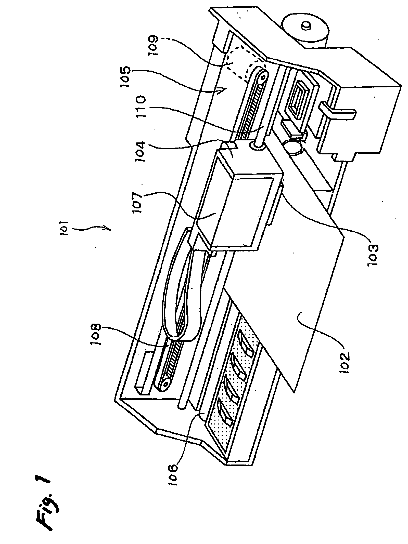
[0074] As shown in FIG. 1, a printer 101 is an apparatus which ejects liquid ink onto the surface of a recording medium 102, such as recording paper or the like, so as to record images or the like. The printer 101 is provided with an ink jet type recording head 103 (hereinafter, is referred to as recording head) which ejects ink, a carriage 104 on which the recording head 103 is mounted, a carriage moving mechanism 105 which moves the carriage 104 in a primary scanning direction, and a platen roller 106 which transfers the recording medium 102 in a secondary scanning direction. Here, ink, which is a type of liquid of the present invention, is stored in an ink cartridge 107. The ink cartridge 107 can be detachably mounted with respect to the recording head 103.

[0075] The carriage moving mechanism 105 is provided with a timing belt 108, which is driven by a pulse motor 109, such as a direct-current (DC) motor. Therefore, if the pulse motor 109 operates, the carriage 104 is guided to ...

second embodiment

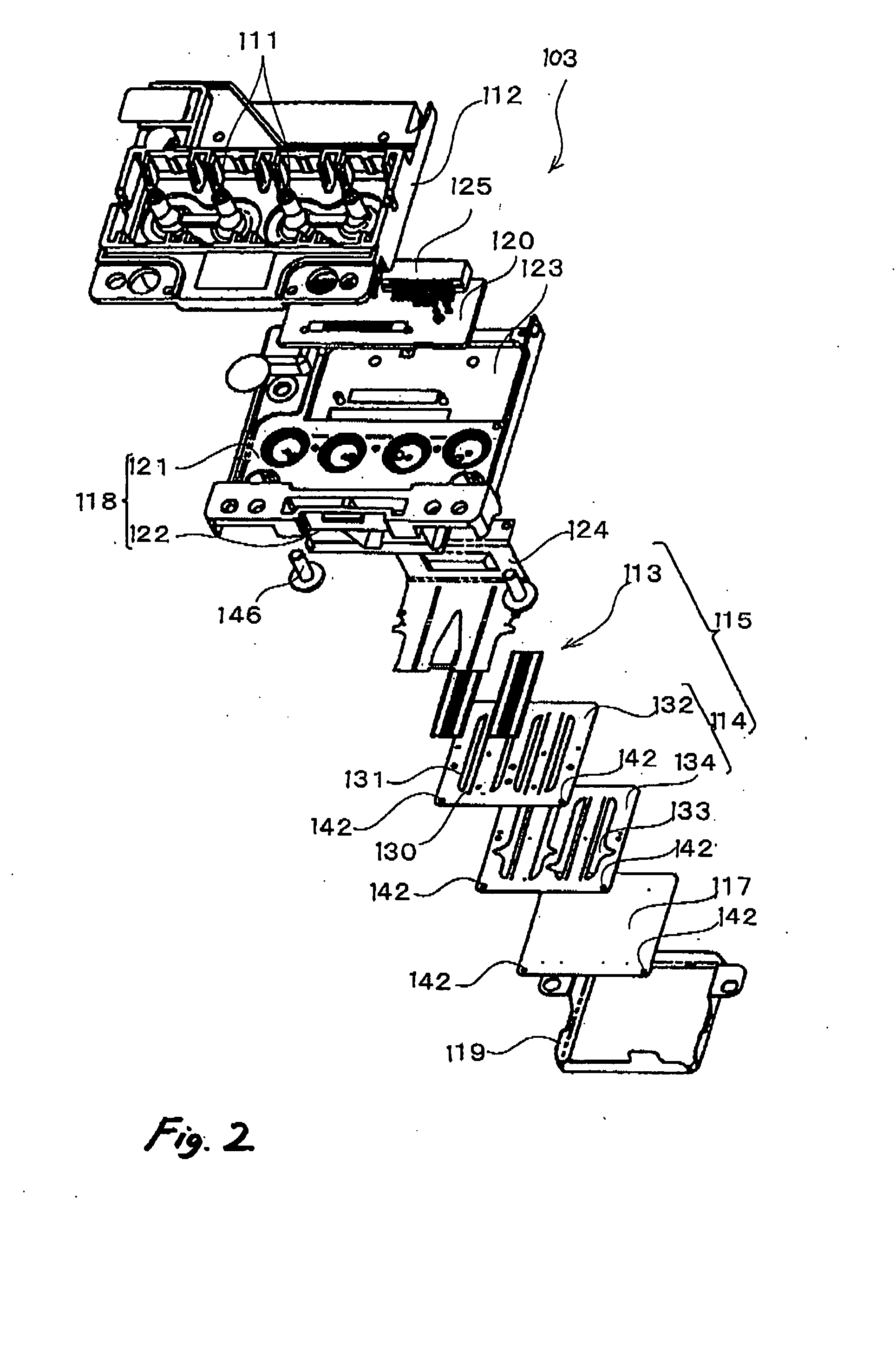
[0100] Next, the invention will be described. As shown in FIGS. 8 to 10, an ink jet type recording head 1 is provided with a head case 16 in which a piezoelectric vibrator 14 is housed, a flow passage unit 26 which is fixed to a unit fixing face of the head case 16 by an adhesive, and a head cover 27 which covers the flow passage unit 26.

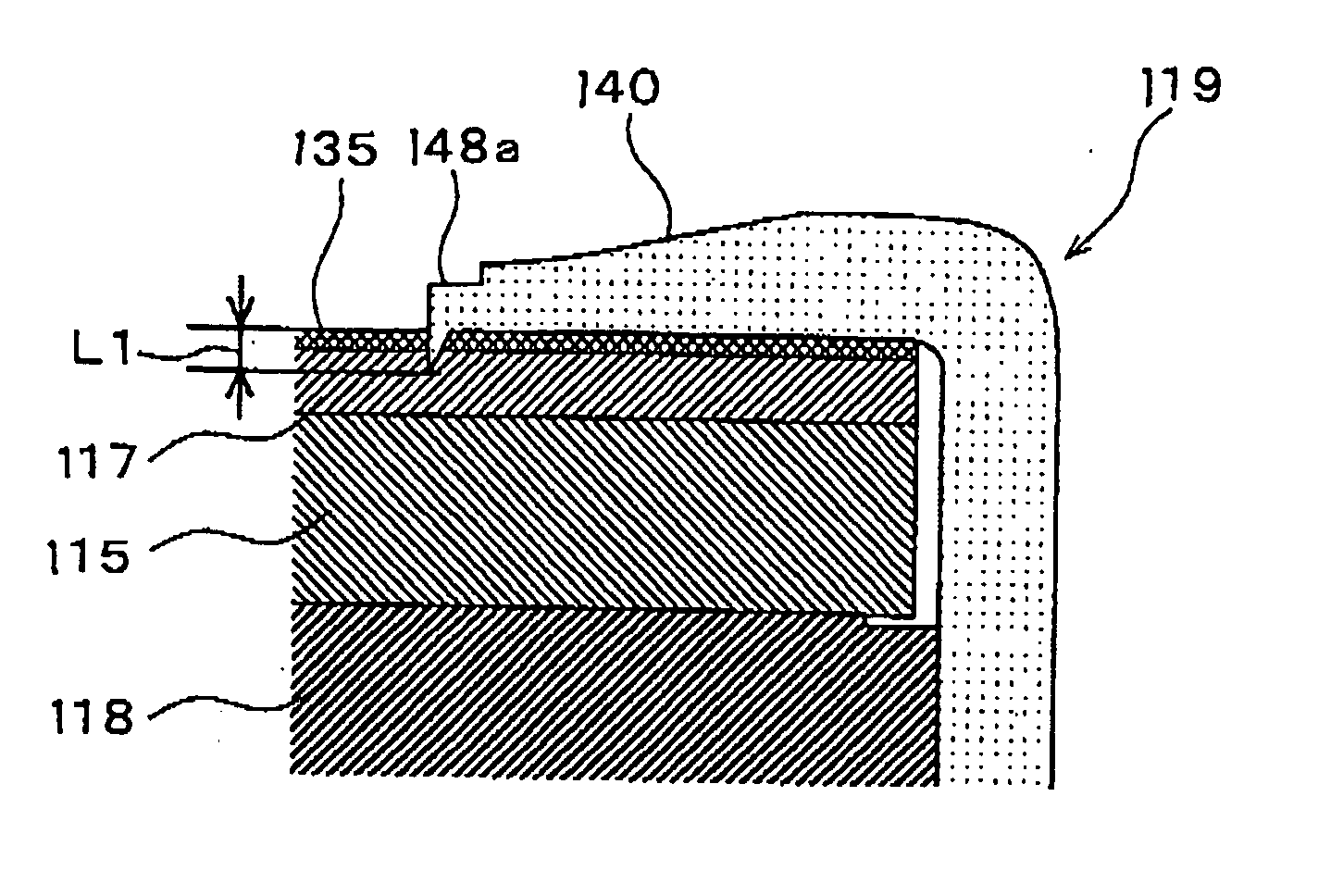
[0101] The flow passage unit 26 is a laminated body of a flow passage forming substrate 11 in which a flow passage space including pressure generating chambers 19 arranged and an ink reservoir 17 for storing ink to be supplied to the individual pressure generating chambers 19, a nozzle plate 10 which is laminated on one surface of the flow passage forming substrate 11 and which has nozzle orifices 15 to eject ink within the pressure generating chambers 19, a vibration plate (sealing plate) 12 which is laminated on the other surface of the flow passage forming substrate 11 to seal the flow passage space including the pressure generating chambers 19. ...

third embodiment

[0187] In this embodiment, arrays of the contact projections 40 may formed in regions close to both edges of the nozzle plate 10 in the primary scanning direction, as in the

[0188] In the above embodiments, the insulating film 37 is a water repellent film. However, various types of insulating films 37, such as a hydrophobic film or the like, may be applied, as long as the film has characteristics suitable for the nozzle formation face 30 of the nozzle plate 10.

[0189] In the above embodiments, a plurality of nozzle plates 10 are cut out from the base material plate 41 by pressing. However, various methods, other than pressing, such as laser cutting and the like, may be used.

[0190] In the above embodiments, the piezoelectric vibrator 14 is used as the pressure generating element. However, a Bubble Jet (Registered Trademark) type ink jet recording head in which liquid within a pressure generating chamber is heated to generate bubbles may be used.


PUM

PropertyMeasurementUnit
thicknessaaaaaaaaaa
thicknessaaaaaaaaaa
heightaaaaaaaaaa

Abstract

A conductive nozzle plate is formed with a nozzle orifice. An insulative layer is formed on a first face of the nozzle plate. A head body includes a pressure chamber adapted to contain liquid therein and a pressure generating element operable to cause pressure fluctuation in the liquid. The head body is attached to a second face of the nozzle plate so as to communicate the pressure chamber with the nozzle orifice. The second face of the nozzle plate and the head body are fixed to a head case. A conductive head cover covers a part of the first face of the nozzle plate while exposing the nozzle orifice. A part of the nozzle plate and the head cover directly come into contact with each other.

Description

BACKGROUND OF THE INVENTION [0001] The present invention relates to a liquid ejecting head, such as an ink jet type recording head, and more particularly, to a liquid ejecting head which is provided with a nozzle forming member having a plurality of nozzle orifices formed thereon and which can eject liquid from the nozzle orifices in forms of liquid droplets. The present invention also relates to a method of manufacturing such a liquid ejecting head. [0002] As a liquid ejecting head which causes a pressure change of liquid within a pressure chamber so as to eject liquid droplets from the nozzle orifices, for example, an ink jet type recording head which is used in an image recording apparatus, such as a printer or the like, a color material ejecting head which is used for manufacturing a color filter of a liquid crystal display or the like, an electrode material ejecting head which is used for forming electrodes of an organic electroluminescent (EL) display, a field emission display...

Claims


Application Information

Patent Timeline
Patent Type & Authority Applications(United States)
IPC IPC(8): B41J2/045
CPCB41J2/1433Y10T29/49401B41J2002/14362
Inventor SHIBUYA, HIROKAZUKOIKE, YASUNORIOKAZAWA, NORIAKIOKUBO, KATSUHIROKO, GAKUAKATSU, TATSUOYAMASHITA, TAKATERU
Owner SEIKO EPSON CORP
Why Eureka
Try Eureka