Electronic function part mounted body and method of manufacturing the electronic function part mounted body

Inactive Publication Date: 2006-09-21
ALPS ALPINE CO LTD
View PDF11 Cites 14 Cited by
  • Summary
  • Abstract
  • Description
  • Claims
  • Application Information

AI Technical Summary

Benefits of technology

[0026] Further, in the present invention, it is preferable to replace the electronic function part or the substrate which is determined to have failed by the inspection with a new electronic function part or substrate, and conduct the inspection again. For example, if the inspection is conducted after the substrate and the electronic function part are heated, adhered, and fixed together, and if the result of the inspection is

Problems solved by technology

However, in U.S. Pat. No. 6,517,362, there is no specific description o

Method used


Image

  • Electronic function part mounted body and method of manufacturing the electronic function part mounted body
  • Electronic function part mounted body and method of manufacturing the electronic function part mounted body
  • Electronic function part mounted body and method of manufacturing the electronic function part mounted body

Examples


Embodiment Construction

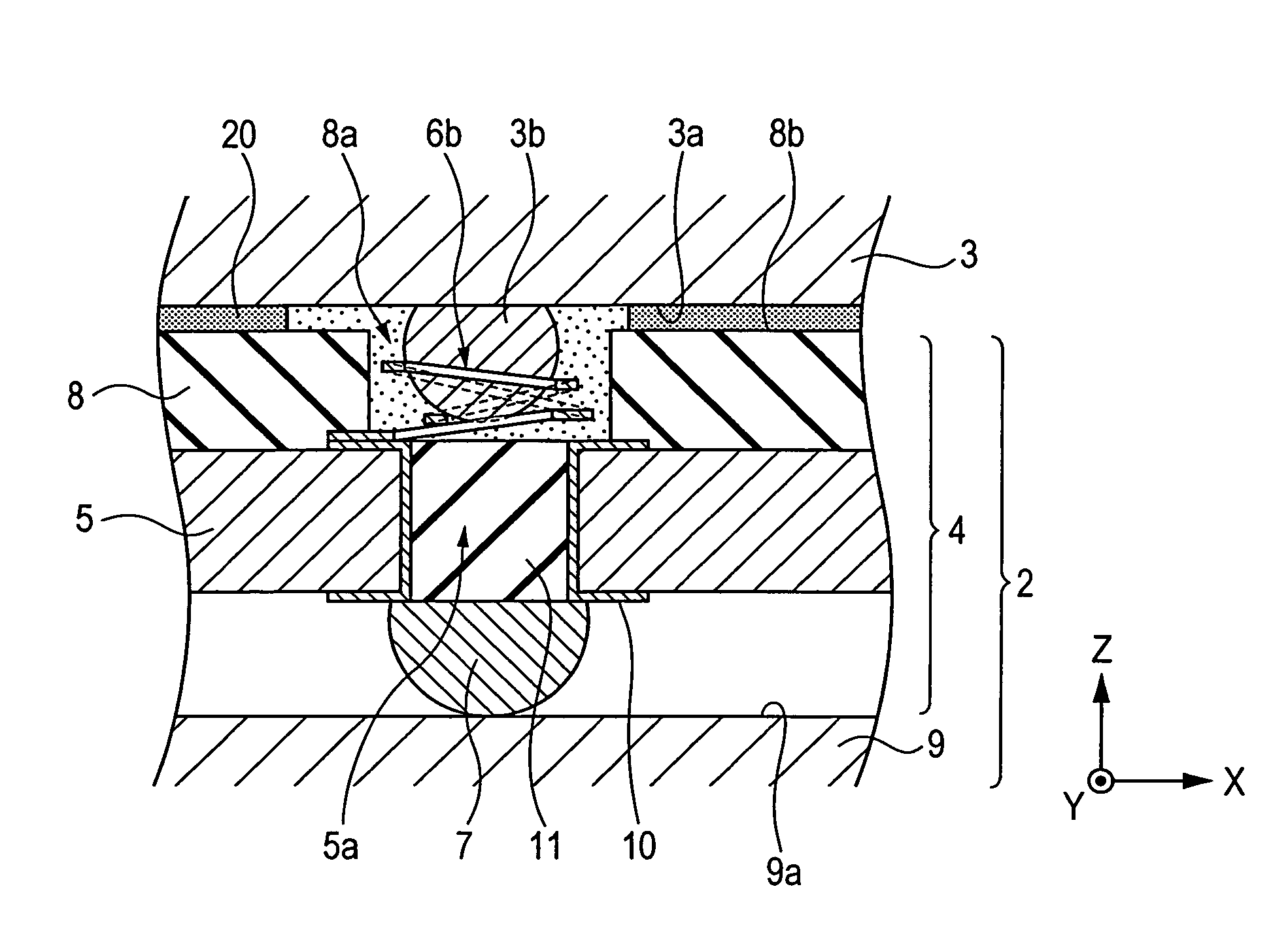
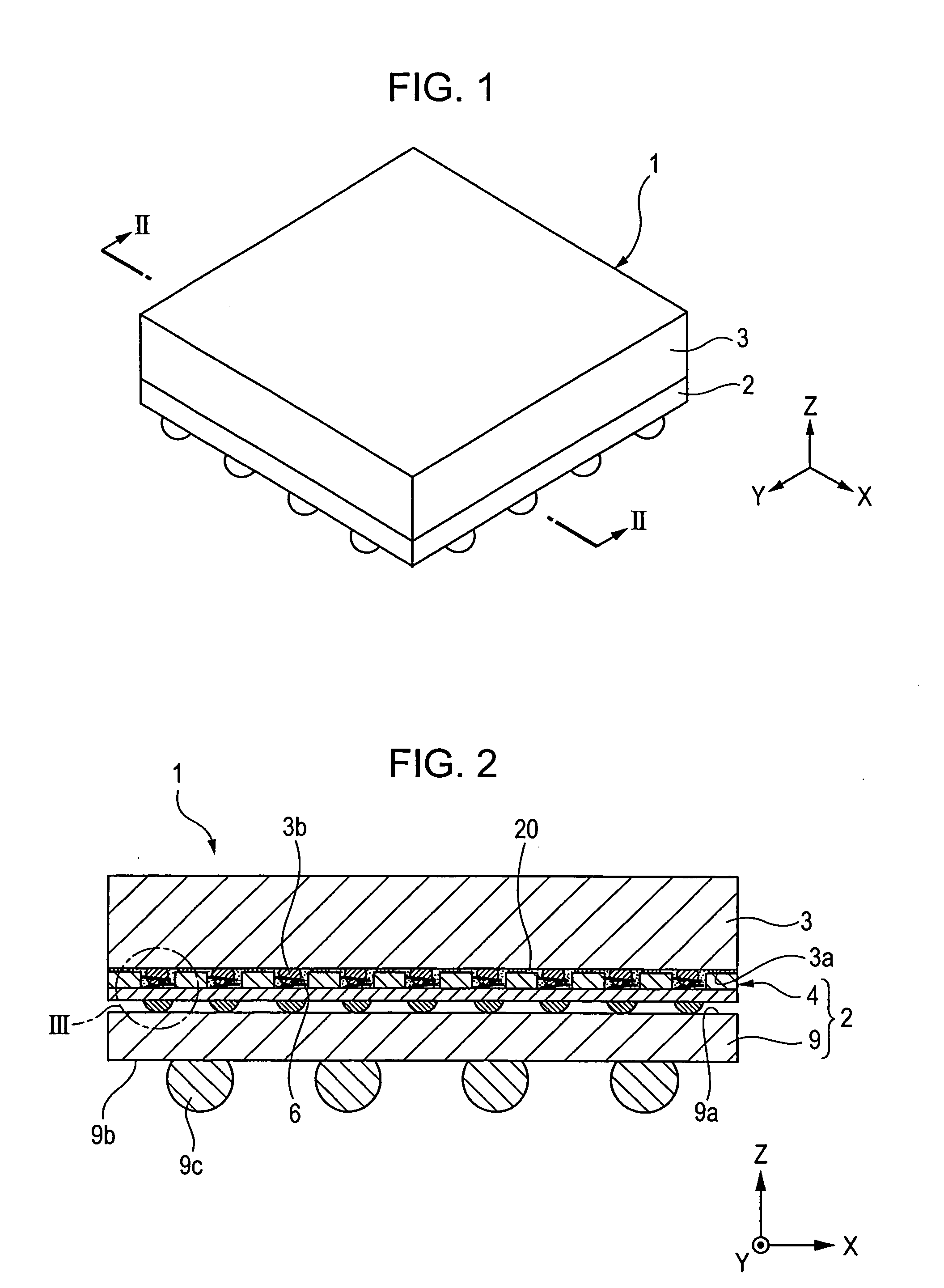
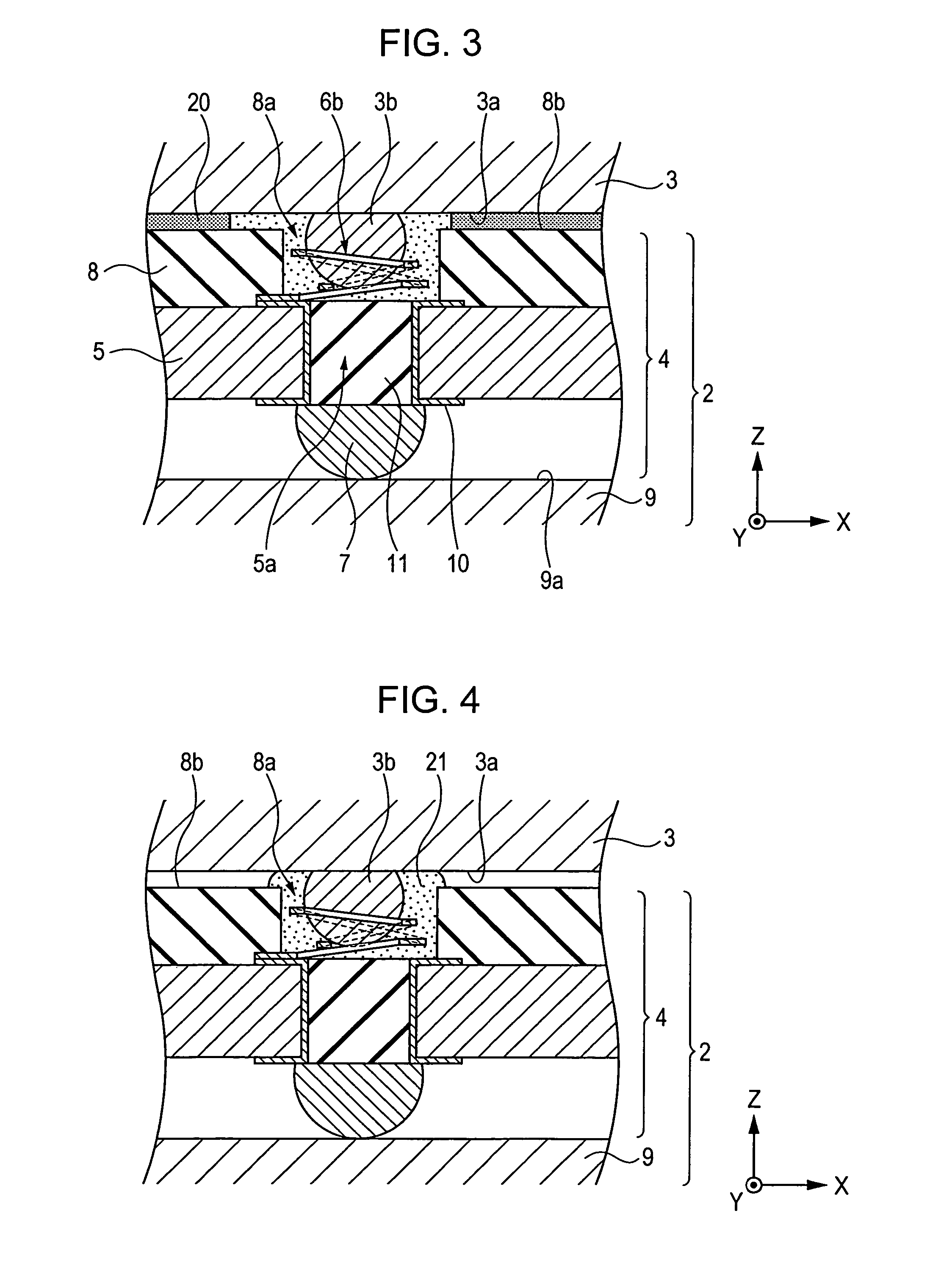
[0041]FIG. 1 is a perspective view of an electronic module (electronic function part mounted body) according to a first embodiment of the present invention, FIG. 2 is a partially sectional view of the electronic module taken along the line II-II shown in FIG. 1 in a direction parallel to the Z direction (thickness direction) and viewed from the direction indicated by arrows, FIG. 3 is a partially enlarged cross-sectional view of the electronic module showing an enlargement of the circled B region in FIG. 2, FIG. 4 is a partially enlarged cross-sectional view of an electronic module for explaining a structure different from the structure shown in FIG. 3, FIG. 5 is a partially enlarged cross-sectional view of an electronic module for explaining a structure different from the structure shown in FIG. 3 or 4, FIG. 6 is a partial plan view showing a surface of a substrate for particularly explaining an adhesion region according to the embodiment of FIG. 3, FIG. 7 is a partial plan view sh...


PUM


Abstract

A spiral contactor is provided on a substrate. An electronic function part and the substrate are adhered with an anisotropic conductive paste while an electrode portion of the electronic function part is being contacted with the spiral contactor. Thus, the electronic function part and the substrate can be securely fixed together while an adequate electrical connection between the electrode portion of the electronic function part and the spiral contactor is ensured.

Description

BACKGROUND OF THE INVENTION [0001] 1. Field of the Invention [0002] The present invention relates to an electronic function part mounted body in which an electronic function part such as a bare chip is mounted on a substrate, and a method of manufacturing the electronic function part mounted body. [0003] 2. Description of the Related Art [0004] An electronic part which uses a spiral contactor is disclosed in U.S. Pat. No. 6,517,362 (see FIG. 23 and FIG. 24, from column 13, line 60 to column 14, line 22). [0005] In U.S. Pat. No. 6,517,362, an electronic part in which a printed wiring board and a spiral contactor provided on a connector cable are connected together is disclosed. [0006] However, in U.S. Pat. No. 6,517,362, there is no specific description of how to fix and hold the printed wiring board and the connector cable. It is required to adequately ensure an electrical connection between the spiral contactor and an electrode portion (in U.S. Pat. No. 6,517,362, referred to as a ...

Claims


Application Information

Patent Timeline
IPC IPC(8): G02B6/00
CPCH01L23/49816H01L24/16H01L24/72H01L24/83H01L24/90H01L2224/1134H01L2224/13099H01L2224/16237H01L2224/73204H01L2224/838H01L2924/01005H01L2924/01029H01L2924/01056H01L2924/01078H01L2924/0781H01L2924/15311H05K3/326H05K3/4015H05K2201/10265H05K2201/10378H05K2201/10719H05K2201/10734H05K2201/10977H01L2924/00014H01L24/29H01L2924/00013H01L2924/01006H01L2924/01033H01L2924/014H01L2224/81899H01L24/73H01L24/81H01L24/91H01L2224/73203H01L2224/81903H01L2924/00011H01L2924/00012H01L2224/0401
Inventor SOETA, KAORU
Owner ALPS ALPINE CO LTD
Why Eureka
Try Eureka