Hand tool for wires

a technology of hand tools and wires, applied in the field of hand tools, can solve the problems of taking a long time to fasten or thread or release the fasteners, and the wires or cables may not be used to operate or treat them of different sizes or diameters,

Active Publication Date: 2008-04-01
HSUN WANG IND
View PDF9 Cites 24 Cited by
  • Summary
  • Abstract
  • Description
  • Claims
  • Application Information

AI Technical Summary

Benefits of technology

[0011]The other objective of the present invention is to provide a hand tool including a quickly changeable structure for allowing bases or jaws to be easily and readily and quickly changed without fastening or releasing fasteners and without driving tools.
[0014]The orifices of the plates of the first and the second levers include a non-circular cross section, and the protrusions of the bars include a non-circular cross section for engaging into the non-circular orifices of the plates of the first and the second levers and for preventing the bars from being rotated relative to the plates of the first and the second levers.
[0016]The extension of the tool device includes a width smaller than that of the tool device for forming at least one shoulders therein. The extension of the tool device includes a serrated surface formed thereon for facilitating a movement of the tool device relative to the plates of the second lever.
[0018]One or more further tool devices may further be provided and changeably attached to the carrier end of the second lever when the tool device is disengaged from the carrier end of the second lever. The further tool devices each also include an extension extended therefrom for selectively engaging into the channel of the second lever, and include a slot formed therein for selectively receiving the bar of the second lever, and include a depression formed therein and communicating with the slot of the tool device for selectively receiving the spring-biased projection of the bar of the second lever, and for anchoring the tool device to the carrier end of the second lever and for preventing the tool device from being moved relative to the plates of the second lever.

Problems solved by technology

However, the opposing edges of the other ends of the levers having the sharp-edged arcuate recesses formed and provided thereon are solidly formed and secured to the handles or hand grips of the levers and may not be disengaged from the levers, such that the levers may not be used to operate or treat the wires or cables of different sizes or diameters.
In addition, it may take a long time to fastened or threaded or released the fasteners.

Method used


Image

  • Hand tool for wires
  • Hand tool for wires
  • Hand tool for wires

Examples


Embodiment Construction

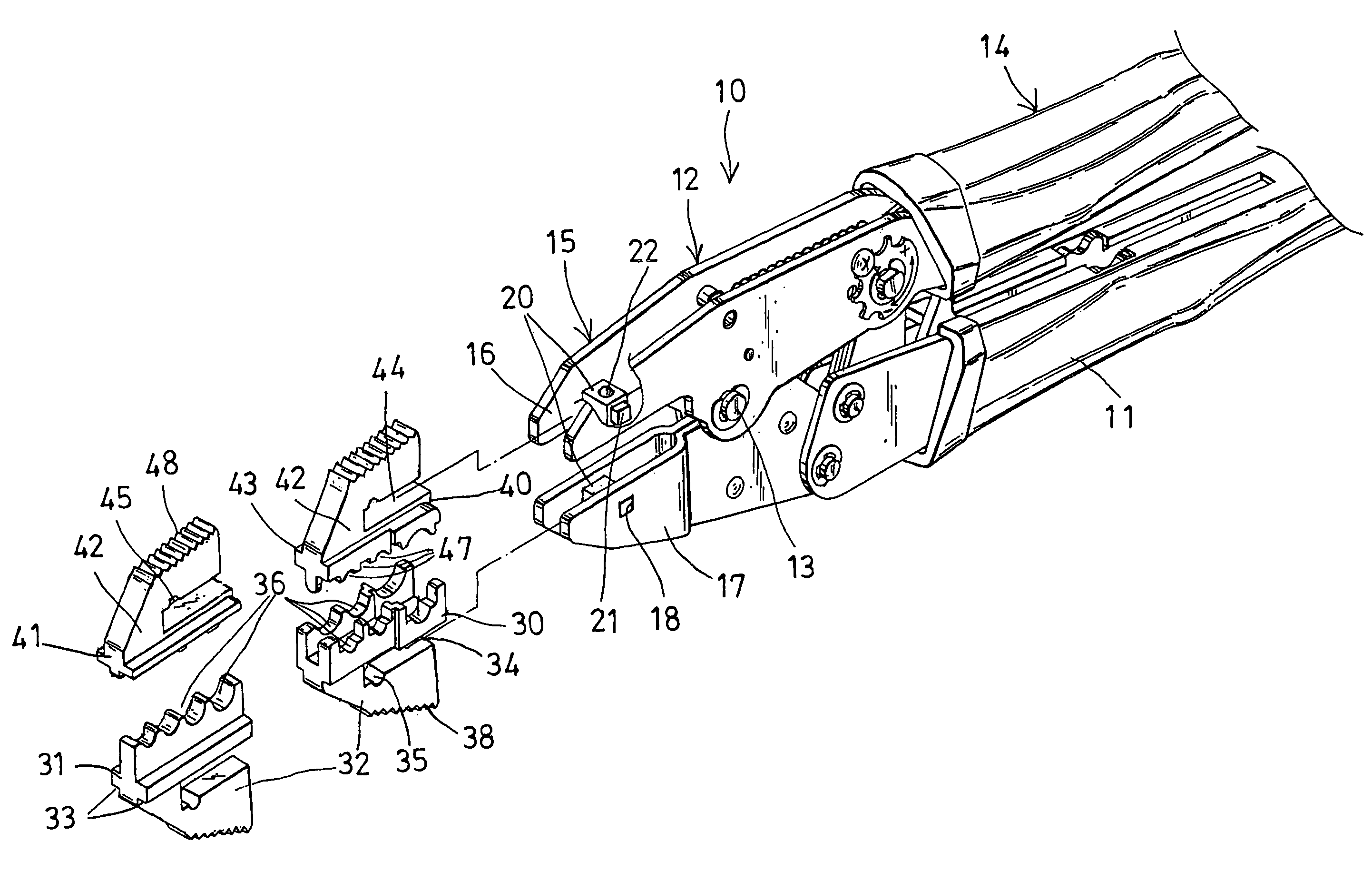
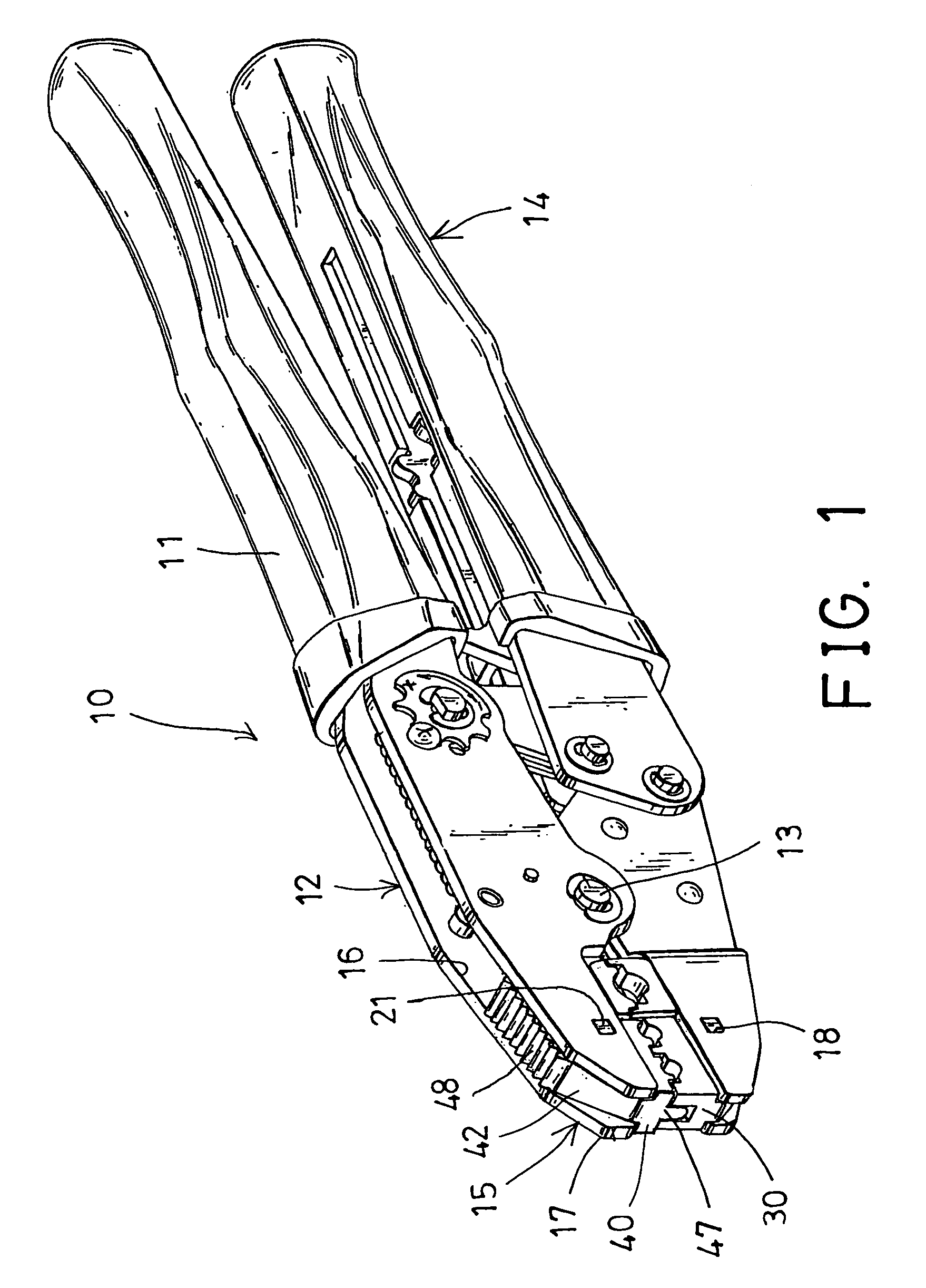
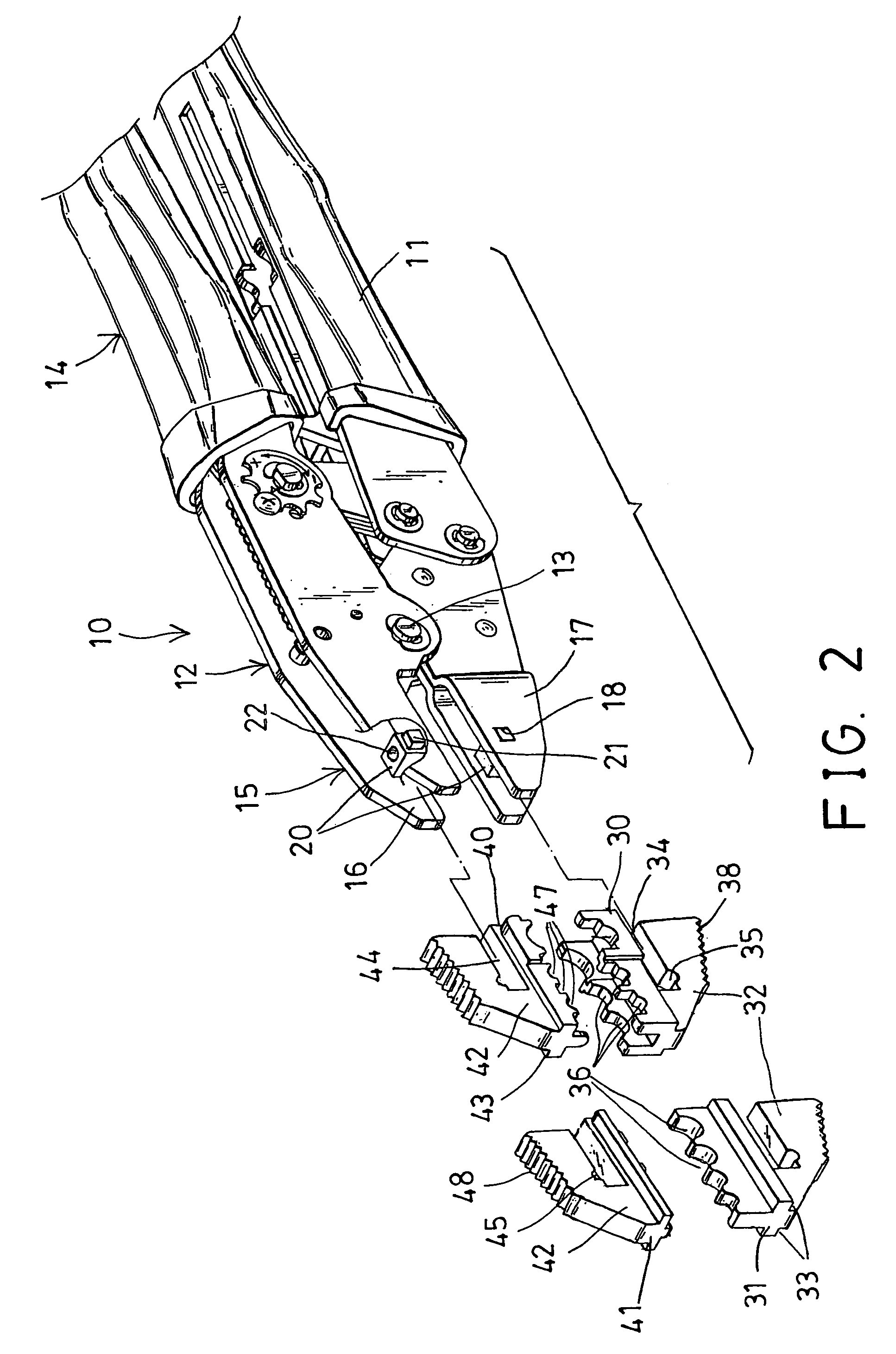
[0022]Referring to the drawings, a hand tool 10 in accordance with the present invention comprises a pair of or two levers 11 pivotally coupled or secured together at a middle portion 12 thereof with a pivot axle 13, and the levers 11 include one end 14 provided or formed or acted as hand grips or handles 14 for being held and grasped by the users, and the other or carrier end 15 for conducting the wire or cable gripping, pulling, bending, stripping, cutting, pressing, crimping, or shearing operations. It is preferable that each of the levers 11 include a channel 16 formed in the other or carrier end 15 thereof and defined between two side walls or plates 17.

[0023]A bar 20 is to be engaged into the channel 16 of each of the levers 11, and to be attached to or secured between the plates 17. For example, the plates 17 of each of the levers 11 include an orifice 18, such as a non-circular orifice 18 formed therein, and each of the bars 20 include one or two protrusions 21 engaged into ...


PUM

PropertyMeasurementUnit
widthaaaaaaaaaa
movementaaaaaaaaaa
sizesaaaaaaaaaa

Abstract

A hand tool includes two levers pivotally coupled together at a middle portion with an axle, and each having a handle end for being held by users, and a carrier end having a channel formed between two plates, a bar is engaged into the channel and secured between the plates of each of the levers and includes a spring-biased projection, one or more supporting members and one or more tool devices may be changeably attached to the levers and include a slot for receiving the bar and a depression for receiving the spring-biased projection, and for changeably attaching the supporting members and the tool devices to the levers without additional fasteners and driving tools.

Description

BACKGROUND OF THE INVENTION[0001]1. Field of the Invention[0002]The present invention relates to a hand tool, and more particularly to a hand tool for wire stripping or cutting or pressing or crimping purposes and / or for pressing and securing cable or wire ends together and including a quickly changeable structure for allowing bases or jaws to be easily and quickly changed without fasteners and without driving tools.[0003]2. Description of the Prior Art[0004]Various kinds of typical hand tools have been developed for gripping, pulling, bending, stripping, cutting, crimping, or shearing wires or cables, and comprise a pair of levers pivotally coupled or secured together at a middle portion thereof, and the levers includes one end formed or acted as handles or hand grips for being held and grasped by the users, and the other end having an anvil and / or a cutting tool or crimping tool or other tools attached thereto for conducting the wire or cable gripping, pulling, bending, stripping,...

Claims


Application Information

Patent Timeline
Patent Type & Authority Patents(United States)
IPC IPC(8): B21D37/14H01R43/042
CPCB25B7/04H02G1/005B25B27/146Y10T29/53226H01R43/042
Inventor LI, YU HSIN
Owner HSUN WANG IND
Why Eureka
Try Eureka