
Container

a container and plastic technology, applied in the field of containers, can solve the problems of affecting the quality of plastic containers, occupying too much space in rigid containers, and bursting on metal molds, etc., and achieves the effect of simple and easy setup

Inactive Publication Date: 2008-04-01
KYORAKU CO LTD
View PDF14 Cites 9 Cited by
  • Summary
  • Abstract
  • Description
  • Claims
  • Application Information

AI Technical Summary

Benefits of technology

The invention is a collapsible container that can be easily stored when not in use. It is made with a sharply decreased burr and has a compact size when folded. The container is made from durable materials, such as plastic, and its components are easily, inexpensively, and speedily fabricated. It can be produced with minimal amount of factory space and is constructed from hollow double wall structure. The container is designed to be secure and stable when erected and uses stopping structures to hold the walls in position. It also has an open top and is easy to setup and use.

Problems solved by technology

Rigid containers occupy too much space and are difficult to work with when stacked.
The method of making the container walls results in a burr on the metal mold, and suffers from a low luminous efficacy rate of effective resin, and a metal mold size that is large.
In the assembly type container disclosed in JP-A No. 63-82941 or JP-A No. 2958339, as the container is disassembled, the side walls are spread flat around the bottom wall of the container, but it is bulky and difficult to stow away, store or carry.
In addition, the side walls are linked to the bottom wall by the thin hinges, and if a load is applied to the side walls in the downward direction, the load is borne by the thin hinges, and more easily broken.
Despite the advantages of the prior art container design, these designs lack a mechanism for holding the side walls securely in the upright position.
For example, the container side walls tend to collapse in the process of fastening the mutually adjacent upright side walls.
This prior art container design is therefore difficult for one person to assemble and requires more time in forming the container.

Method used


Image

  • Container
  • Container
  • Container

Examples


Embodiment Construction

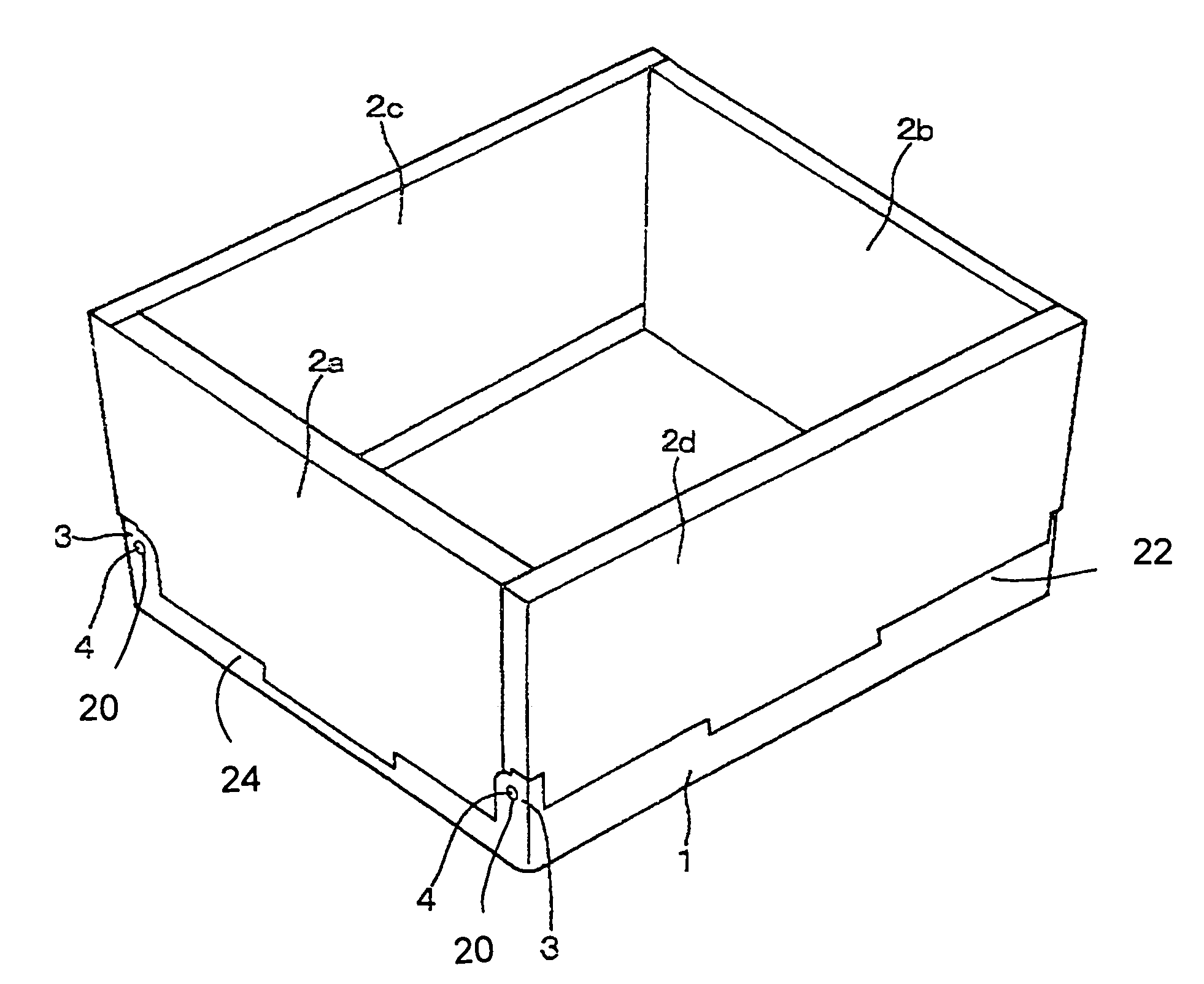
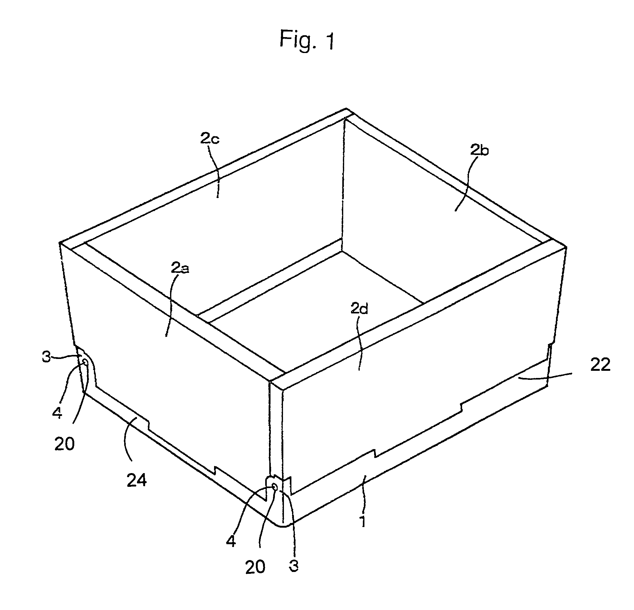
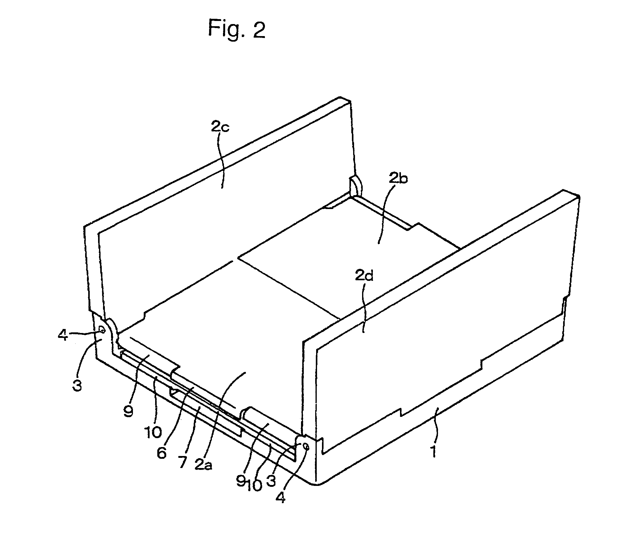
[0041]The preferred embodiment of the invention is a collapsible container as illustrated in FIG. 1. Referring to FIG. 1, a base section 1, is connected to first 2a and second 2b end walls and first 2c and second 2d side walls. The sections and walls, 1, 2a, 2b, 2c, 2d are manufactured using hollow double-frame construction and are composed of thermoplastic, such as polyethylene, polypropylene, or other engineered plastic, that has been blow molded. Thus the walls are lightweight and capable of a multitude of complex shapes and sizes. While it is noted that the sections are labeled end walls and side walls, it is readily apparent that the container can be a square having equal length end walls and side walls. The label of end wall is generally applied to the pair of opposing walls that are shorter in length than the pair of side walls. While shown as a rectangle in FIG. 1, there are other shapes that can benefit from the advantages of the present invention.

[0042]In the preferred emb...


PUM


Abstract

An open top box-shaped container is provided having a pair of confronting end walls tiltably pivoted and coupled to a bottom wall, wherein the end walls are pivoted at the bottom wall so as to be folded in contact with a top of the bottom wall, a pair of side walls are tiltably pivoted and coupled to the bottom wall so as to be folded in contact with a top of the end walls, wherein a side stopping protrusion is formed on a pivoting side edge of the side walls, that side stopping protrusion being a sectional U shape, such that when the side wall is in an erect position a side stopping groove on the bottom wall mates with each side stopping protrusion to form an erect side stopping structure.

Description

CROSS REFERENCE TO RELATED APPLICATIONS[0001]This application claims priority under 35 U.S.C. Section 365(c) of the PCT International application PCT / JP00 / 08416, designating the United States of America, which claims priority from a Japanese Patent Application No. 11-341278 filed on Sep. 30, 1999, which is incorporated herein by reference for all purposes.BACKGROUND OF THE INVENTION[0002]1. Technical Field of the Invention[0003]The present invention relates to a plastic container having foldable side walls with a pivotal structure disposed at each side of a bottom wall capable of forming a box-shaped container with an open top by erecting each side wall, and also capable of being folded when not in use.[0004]2. Background Art[0005]Plastics play an indispensable role in a wide variety of markets, including packaging, building, construction, transportation, consumer and institutional products, furniture and furnishings, electrical / electronic components, adhesives, inks and coatings. T...

Claims


Application Information

Patent Timeline
Patent Type & Authority Patents(United States)
IPC IPC(8): B65D6/16B65D6/12B65D6/18B65D6/26B65D6/28
CPCB65D11/1833B65D7/26
Inventor ENDOU, HARUHIRO
Owner KYORAKU CO LTD
Learn More