Recording apparatus

a recording device and a technology for recording equipment, applied in the field of recording equipment, can solve the problems of inability to stacked the recorded recording medium in the desired state, and the media is more prone to rounding

Active Publication Date: 2015-11-10
SEIKO EPSON CORP
View PDF6 Cites 4 Cited by
  • Summary
  • Abstract
  • Description
  • Claims
  • Application Information

AI Technical Summary

Benefits of technology

[0010]That is to say, the leading end of the discharged recorded medium is guided to the side opposite to the direction of discharge of the recorded medium by the guide surface, at the lower side of the discharge part, and therefore when a plurality of recorded media are discharged, the leading ends of the recording media are aligned and suitably stacked. In a case where the recorded medium being discharged is long, having the guide surface be separable with respect to the discharge part allows for the long recorded medium to be suitable stacked. As such, the above-described aspect makes it possible to provide a recording apparatus with which both a long recorded medium and a short recorded medium can be suitable stacked.
[0014]A rail oriented in the sliding direction of the medium catcher part may be provided, the medium catcher part being slidably mounted onto the rail. This aspect makes it possible to slide the guide surface with the simple configuration of the rail.
[0015]The medium catcher part may have a frame part slidably provided so as to slide to a side of discharge of the recorded medium and an opposite side thereof. The guide surface may be constituted of a sheet member that is mounted onto the frame part and with which a slack part is formed on the lower side of the discharge part. This aspect makes it possible to provide a convenient recording apparatus with which the sliding remains possible while the shape of the slack part is maintained, because the slack part of the sheet member slides in conformity with the sliding of the frame part.
[0016]The medium catcher part may be rotatable about a position of mounting onto the leg part, and may be movable to below the housing with an orientation running along the sliding direction. This aspect makes it possible to provide a recording apparatus with which the medium catcher part can be compactly stowed when not in use, because the medium catcher part can be rotated with an orientation running along its own direction of sliding and moved to below the housing.
[0017]The recording apparatus may be provided, at a lower part of the housing, with a medium support part configured to support supporting the recording medium which is conveyed to the recording part. The medium catcher part, which is further to the side of discharge of the recorded medium than the medium support part, may be able to rotate and move to below the housing with an orientation running along the sliding direction. This aspect allows for favorable access to the recording medium being supported by the medium support part and enables mass recording, because the medium catcher part, which is further to the side of discharge of the recorded medium than the medium support part, can be stowed below the housing.

Problems solved by technology

The case of a short recorded recording medium is more prone to rounding because of the curling of the recorded recording medium.
For this reason, there is the risk of the inability for the recorded recording medium to be stacked in a desired state, such as when the recorded recording medium is stacked in a rounded state.
This problem is not limited to inkjet printers, and similarly affects a variety of recording apparatus.

Method used


Image

  • Recording apparatus
  • Recording apparatus
  • Recording apparatus

Examples


Embodiment Construction

[0028]An embodiment of the present invention shall be described below. It shall be readily understood that the following embodiment is merely for illustratively exemplifying the present invention, and not all of the features illustrated in the embodiment are necessarily essential for the means of solving of the present invention.

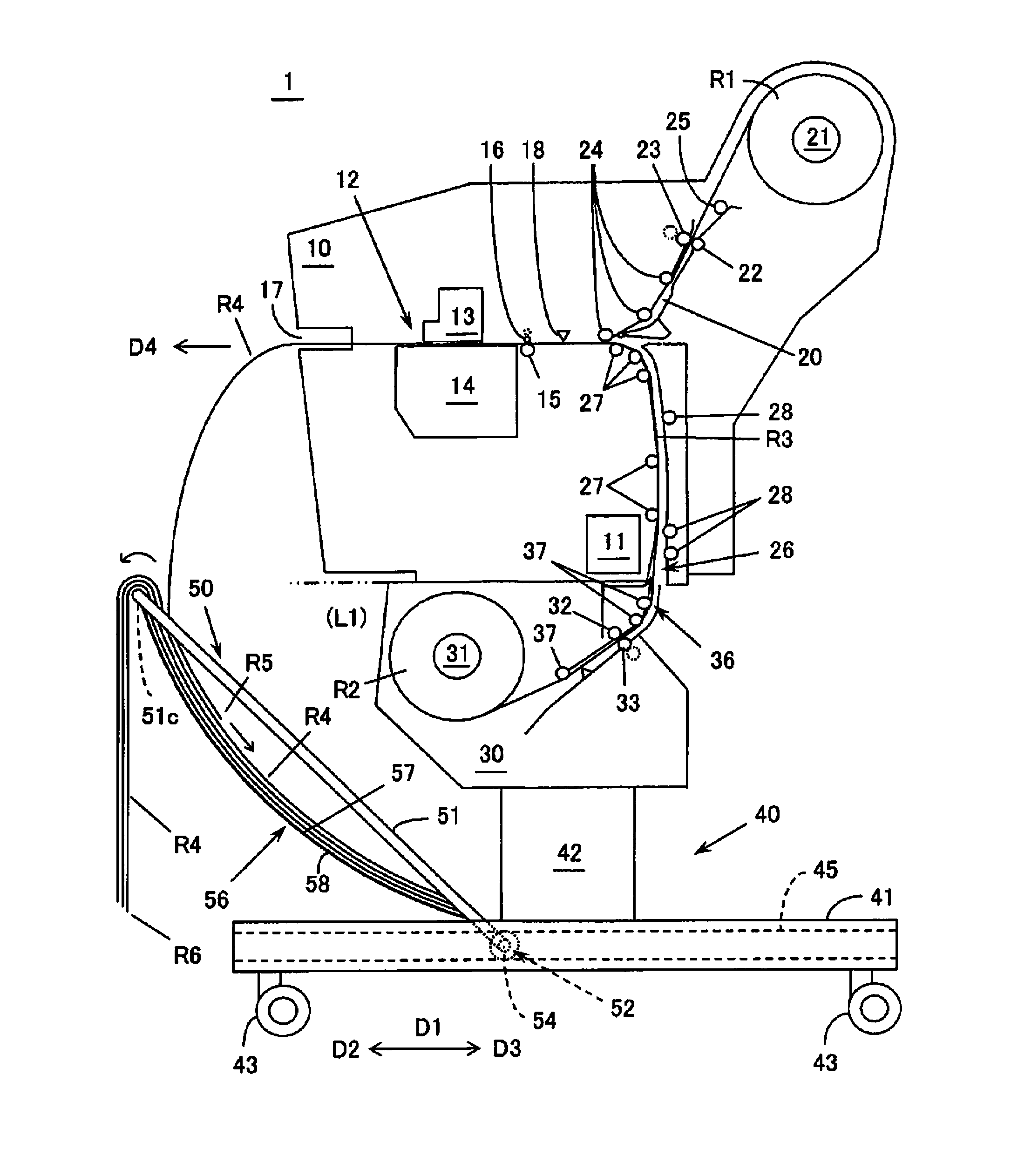
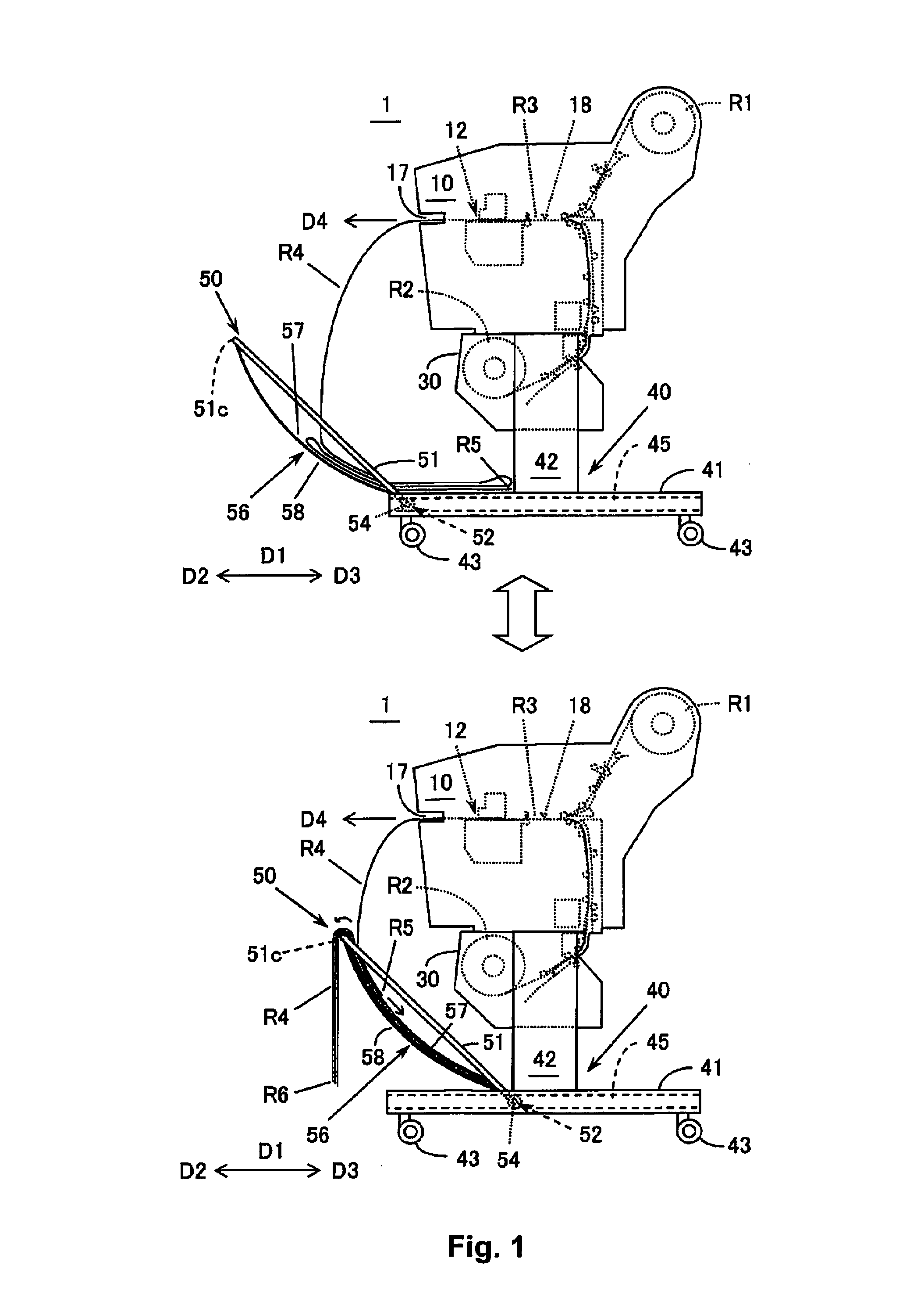
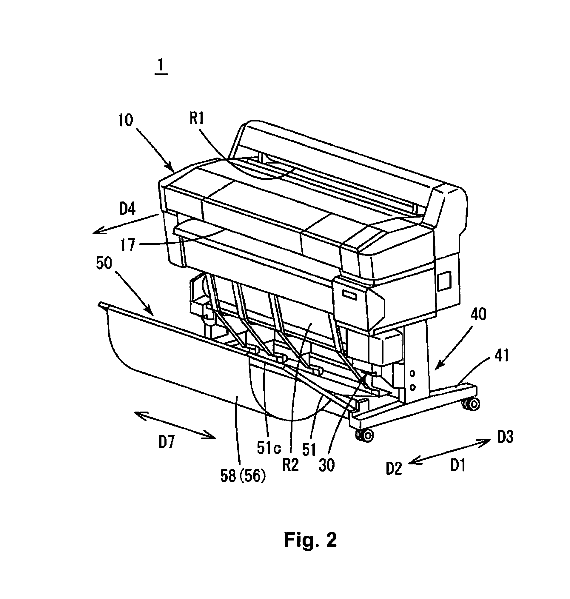
[0029]FIG. 1 is a side view schematically illustrating the manner in which a recorded medium R4 is stacked; the upper drawing illustrates the manner in which a stacker (medium catcher part) 50 is slid in a direction of separation D2 from a discharge part 17, and the lower drawing illustrates the manner in which the stacker 50 is slide in a direction of approach D3 toward the discharge part 17. FIG. 2 is a perspective view illustrating the outer appearance of a large-scale inkjet printer serving as a recording apparatus 1. FIG. 3 is a vertical cross-sectional view illustrating the interior of the recording apparatus with a cross-sectional view of a housing 10...


PUM


Abstract

A recording apparatus includes a recording part configured to record onto a recording medium; a discharge part configured to discharge a recorded medium, which is the recording medium that has been previously recorded on; and a medium catcher part configured to catch the discharged recorded medium. The medium catcher part has a guide surface configured to guide a leading end of the discharged recorded medium toward a side (the direction of approach side) opposite to a discharge direction in which the recorded medium is discharged, at a lower side of the discharge part and is configured so that the guide surface is separable from the discharge part.

Description

CROSS-REFERENCE TO RELATED APPLICATIONS[0001]This application claims priority to Japanese Patent Application No. 2013-063556 filed on Mar. 26, 2013. The entire disclosure of Japanese Patent Application No. 2013-063556 is hereby incorporated herein by reference.BACKGROUND[0002]1. Technical Field[0003]The present invention relates to a recording apparatus.[0004]2. Related Art[0005]Recording apparatuses such as large-scale inkjet printers include one where a recording paper that has been fed out from a roll of paper (a recording medium) is printed on, cut, and discharged from a discharge port, and the recording paper is allowed to fall into a paper catcher below the discharge port. A recorded recording medium catcher disclosed in Japanese Laid-open Patent Publication H7-61681 has a sheet-shaped member, one end of which is supported by a support member that can be pulled out from a leg part of a recording apparatus; the other end of the sheet-shaped member is supported by a hook of the ...

Claims


Application Information

Patent Timeline
Patent Type & Authority Patents(United States)
IPC IPC(8): B65H31/00B65H31/22B41J11/00B41J13/10B41J15/04
CPCB65H31/00B41J11/001B41J13/106B41J15/04B65H31/22B65H2402/31B65H2402/32B65H2405/1122B65H2405/1124B65H2801/36B65H2405/324B65H2701/11312B65H31/02B65H31/20
Inventor HORIE, SEIJUN
Owner SEIKO EPSON CORP
Why Eureka
Try Eureka