Door plate for furnace

a door plate and furnace technology, applied in the field of semiconductor processing, can solve the problem that the contact of quartz and quartz does not make for a completely airtight seal

Active Publication Date: 2008-04-01
ASM INTERNATIONAL
View PDF14 Cites 340 Cited by
  • Summary
  • Abstract
  • Description
  • Claims
  • Application Information

AI Technical Summary

Problems solved by technology

However, quartz contacting quartz does not make for a completely airtight seal.
While effective at minimizing door plate corrosion and process gas leakage, flowing inert gas through the sealing chamber 106 has been observed to detrimentally affect process results on substrates processed in the reaction chamber 104.

Method used


Image

  • Door plate for furnace
  • Door plate for furnace
  • Door plate for furnace

Examples


Embodiment Construction

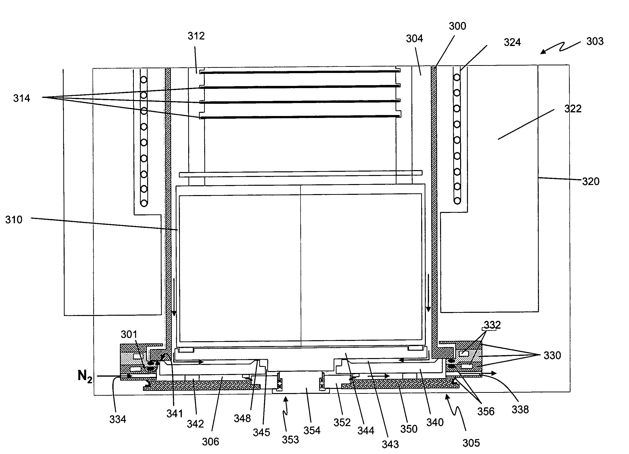
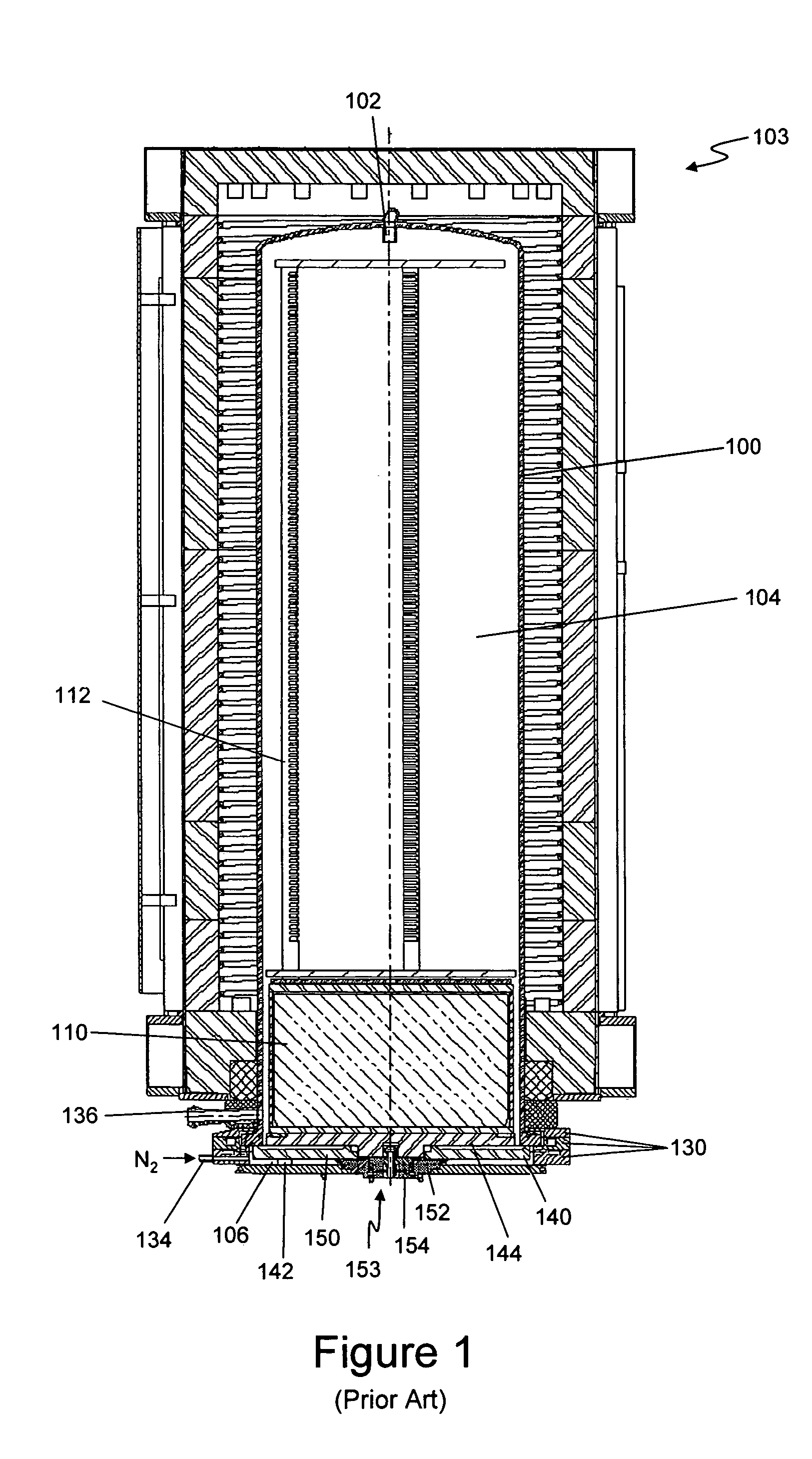
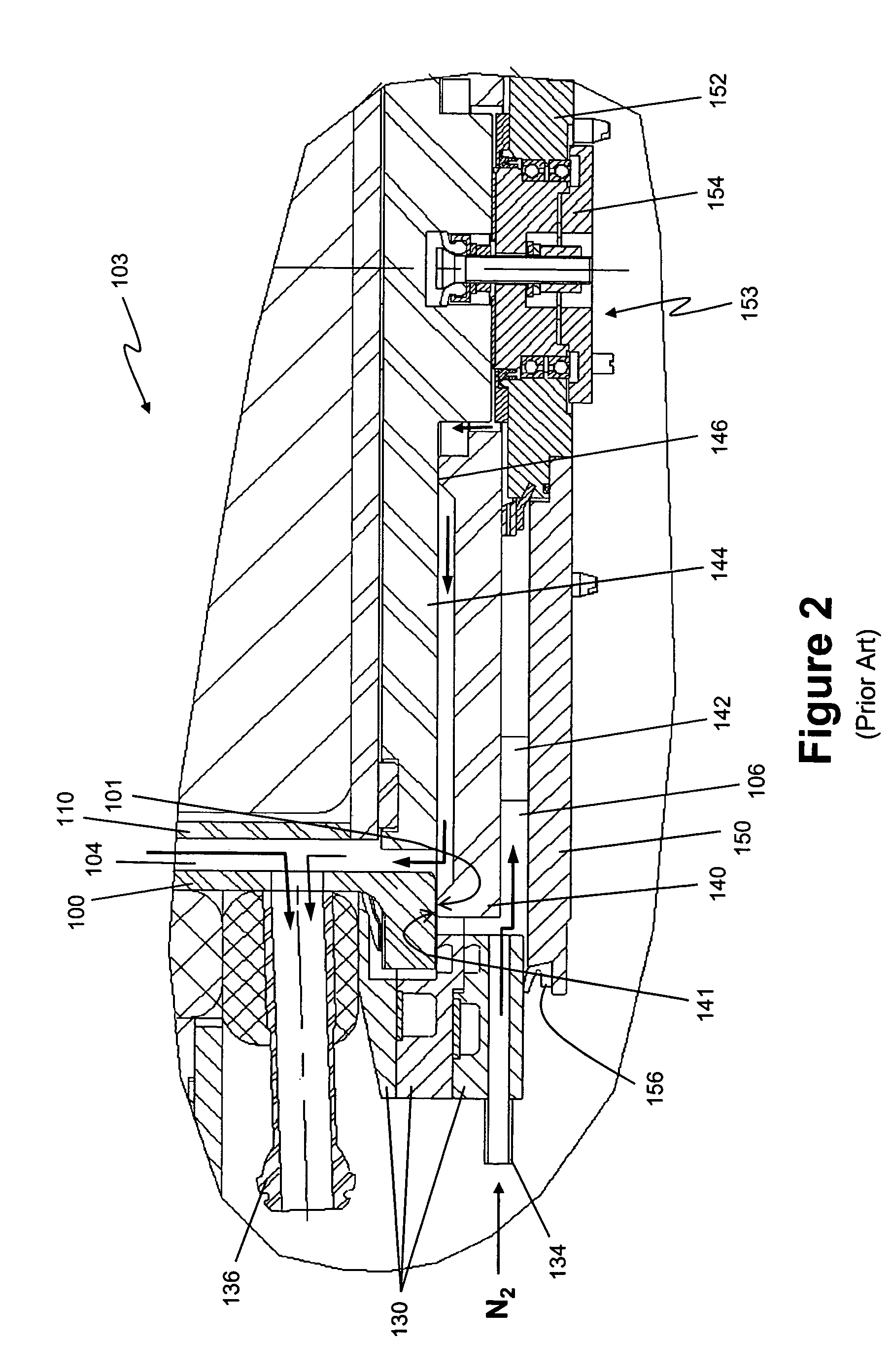
[0024]It has been found that the poor process results in some furnaces, such as those illustrated in FIGS. 1 and 2, are caused by several problems stemming from the design of the furnaces and their closures. First, with reference to FIGS. 1 and 2, where the purge gas in the sealing chamber 106 is lighter than the process gas, buoyancy effects can occur if the purge gas leaks into the process chamber 104. For example, this is the case when the process gas is O2, having a molecular weight of 32, and the purge gas is N2, having a molecular weight of 28. When the purge gas reaches the area in which the substrates are placed, the purge gas can detrimentally influence the uniformity of processes by traveling through the reaction chamber 104 and diluting the process gas. “Bubbles” of purge gas can rise in the process tube 100 and persist, especially at heights near or above the opening of the process gas inlet 102. The purge gas can move through the reaction chamber 104 along particular pa...


PUM


Abstract

The process chamber of a vertical furnace is provided with a closure, or door, comprising an upper and a lower door plate. The upper door plate has a gas exhaust opening proximate its center, thereby allowing for a symmetrical flow of process gases through the process chamber and into the gas exhaust opening. The upper door plate is spaced from the lower door plate to form a sealing chamber, which is purged with inert gas. Optionally, both the gas exhaust opening and the sealing chamber empty into a gas exhaust channel formed inside the upper door plate. The gas exhaust channel leads to an exhaust which exhausts gases from the furnace and separates the flow path of corrosive process gases from surfaces of the lower door plate, which may be formed of relatively easily-corroded metal.

Description

CROSS-REFERENCE TO RELATED APPLICATIONS[0001]This application is related to: U.S. patent application Ser. No. 11 / 038,357, entitled METHOD FOR PURGING SEALS IN A THERMAL REACTOR, filed Jan. 18, 2005; and U.S. patent application Ser. No. 11 / 049,048, entitled METHOD FOR PROCESSING SEMICONDUCTOR SUBSTRATES, filed Feb. 1, 2005. The entire disclosures of these applications are incorporated herein by reference.BACKGROUND OF THE INVENTION[0002]1. Field of the Invention[0003]This invention relates to semiconductor processing and, more particularly, to furnaces used for semiconductor processing.[0004]2. Description of the Related Art[0005]During semiconductor manufacturing, vertical furnaces are commonly used to subject semiconductor substrates, such as wafers, to a number of processing steps, including oxidation and diffusion steps, at elevated temperatures. A heat resistant material in the shape of a cylindrical tube can be used to form the interior walls of the furnaces. The lower end of a...

Claims


Application Information

Patent Timeline
Patent Type & Authority Patents(United States)
IPC IPC(8): F27D1/18
CPCH01L21/67126H01L21/324H01L21/304
Inventor BERENBAK, BARTDE RIDDER, CHRIS G. M.
Owner ASM INTERNATIONAL
Why Eureka
Try Eureka