Electrical box assembly

a technology of electrical boxes and assembly parts, applied in the field of electrical boxes, can solve the problems of increasing the time required to complete the installation process, the installer cannot use nails or screws to mount the electrical boxes to the studs, and the inability to install the electrical boxes correctly, so as to reduce the inventory

Active Publication Date: 2008-04-01
HUBBELL INC
View PDF21 Cites 29 Cited by
  • Summary
  • Abstract
  • Description
  • Claims
  • Application Information

AI Technical Summary

Benefits of technology

[0008]Accordingly, another objective of the present invention is to provide an electrical box that has screw and nail supports to facilitate movement of the electrical box with screws and nails securely attached thereto and to prevent accidental removal of the screws and nails from the electrical box prior to installation.
[0010]The foregoing objects are basically attained by providing an electrical box assembly that includes a base having an outer edge. A wall extends outwardly from the outer edge of the base and forms a cavity therein. A first fastener support on the wall is adapted to receive a first fastener. A second fastener support on the wall is adapted to receive a second fastener. The first and second fasteners are different types of fasteners. The first and second fastener supports allow the electrical box to be mounted to a stud with either a first or second fastener, thereby reducing the inventory by not requiring separate electrical boxes for each type fastener.

Problems solved by technology

One problem with existing electrical boxes is the inability of the installer to use either nails or screws to mount the electrical box to the stud.
Therefore, the installer must ensure he has the proper fasteners for the electrical boxes to be installed, or the electrical boxes cannot be installed correctly.
Additionally, requiring the installer to ensure the correct fastener is available for installation of the existing electrical boxes is inefficient and increases the time required to complete the installation process.
Another problem with existing electrical boxes is that the installer must locate the required mounting fasteners to mount the electrical boxes to the studs.
The mounting fasteners are often lost or separated from the electrical boxes prior to mounting the electrical boxes, thereby increasing the installation time required to mount the electrical boxes.

Method used


Image

  • Electrical box assembly
  • Electrical box assembly
  • Electrical box assembly

Examples


Embodiment Construction

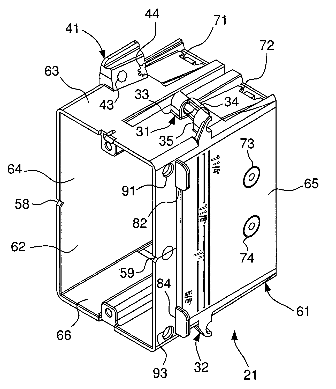
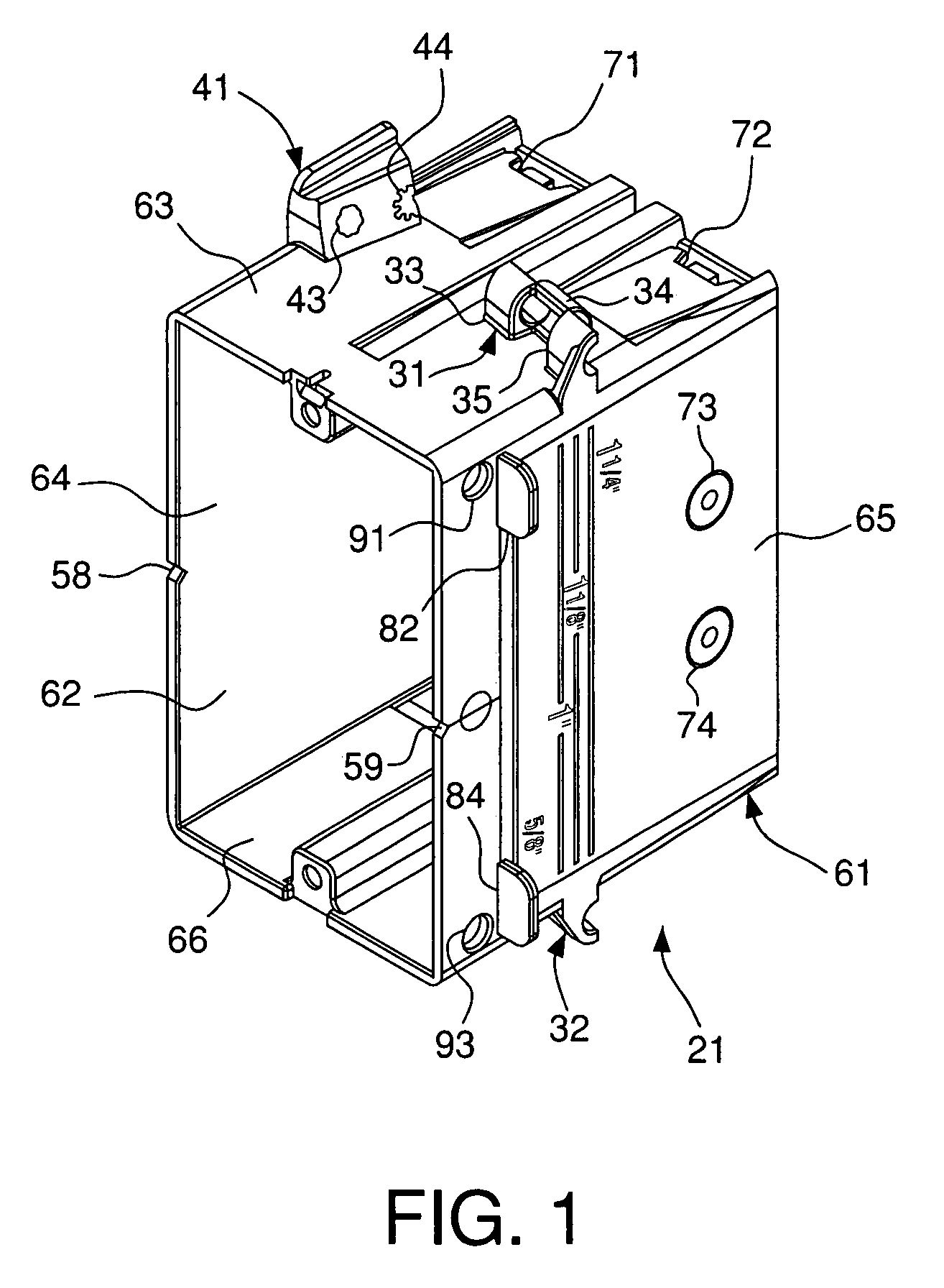
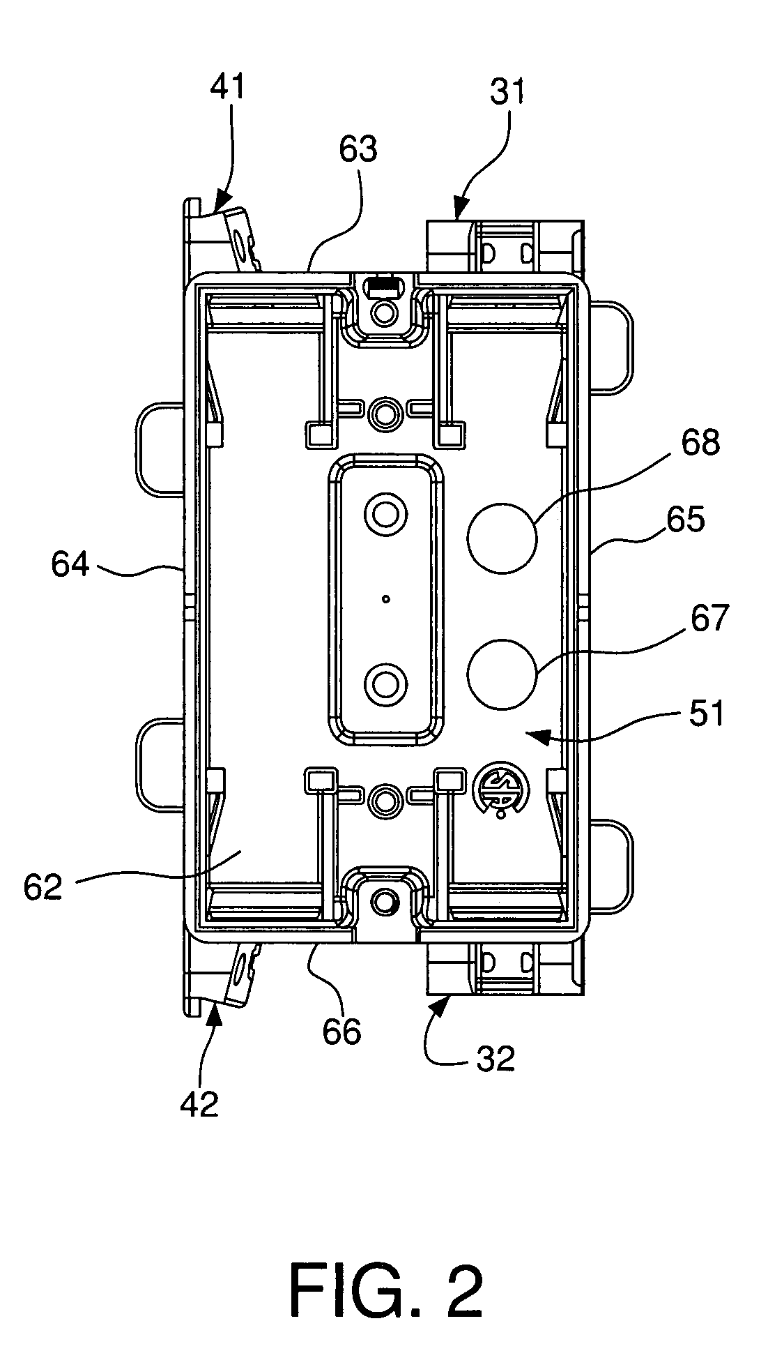
[0043]As shown in FIGS. 1-29, an electrical box assembly 21 according to exemplary embodiments of the present invention has first and second fastener supports 31 and 41, respectively, adapted to receive either a first or second fastener to provide an installer with multiple installation options for an electrical box. The electrical box assembly is adapted to receive two different types of fasteners, such as screws and nails. The electrical box assembly 21 has a base 51 with an outer edge. A wall 61 extends outwardly from the outer edge of the base. A cavity 62 is formed by the wall 61 and the base 51. A first fastener support 31 on the wall 61 is adapted to receive a first fastener. A second fastener support 41 on the wall 61 is adapted to receive a second fastener, wherein the first and second fasteners are different types of fasteners.

[0044]The electrical box assembly 21 has a base 51 with an outer edge from which a wall 61 extends outwardly, as shown in FIGS. 1 and 2. Preferably,...


PUM


Abstract

An electrical box assembly adapted to receive two different types of fasteners, such as screws and nails. The electrical box assembly has a base with an outer edge. A wall extends outwardly from the outer edge of the base that forms a cavity therein. A first fastener support on the wall is adapted to receive a first fastener. A second fastener support on the wall is adapted to receive a second fastener, wherein the first and second fasteners are different types of fasteners.

Description

FIELD OF THE INVENTION[0001]The present invention relates to an electrical box having a plurality of fastener supports to provide an installer with multiple installation options. More particularly, the present invention relates to a single gang electrical box having both nail and screw supports, and having mounting holes to mount additional low voltage frames or mounting brackets after the electrical box has been mounted to a support. Still more particularly, the present invention relates to an electrical box having a plurality of fastener supports in which the fastener supports securely receive the fasteners such that the fasteners may be shipped in position for installation with the electrical box, thereby preventing accidental removal of the fasteners from the electrical box.BACKGROUND OF THE INVENTION[0002]Electrical boxes are typically used in residential, commercial and industrial construction environments to provide accessibility to and control of electrical service. Electric...

Claims


Application Information

Patent Timeline
Patent Type & Authority Patents(United States)
IPC IPC(8): H01H9/02
CPCH02G3/126H02G3/125
Inventor MAGISANO, FRANCESCODI SERIO, ROCCO
Owner HUBBELL INC
Why Eureka
Try Eureka