

Method and apparatus for selection control
- Summary
- Abstract
- Description
- Claims
- Application Information
AI Technical Summary
Benefits of technology
Problems solved by technology
Method used
Image

Examples
first embodiment
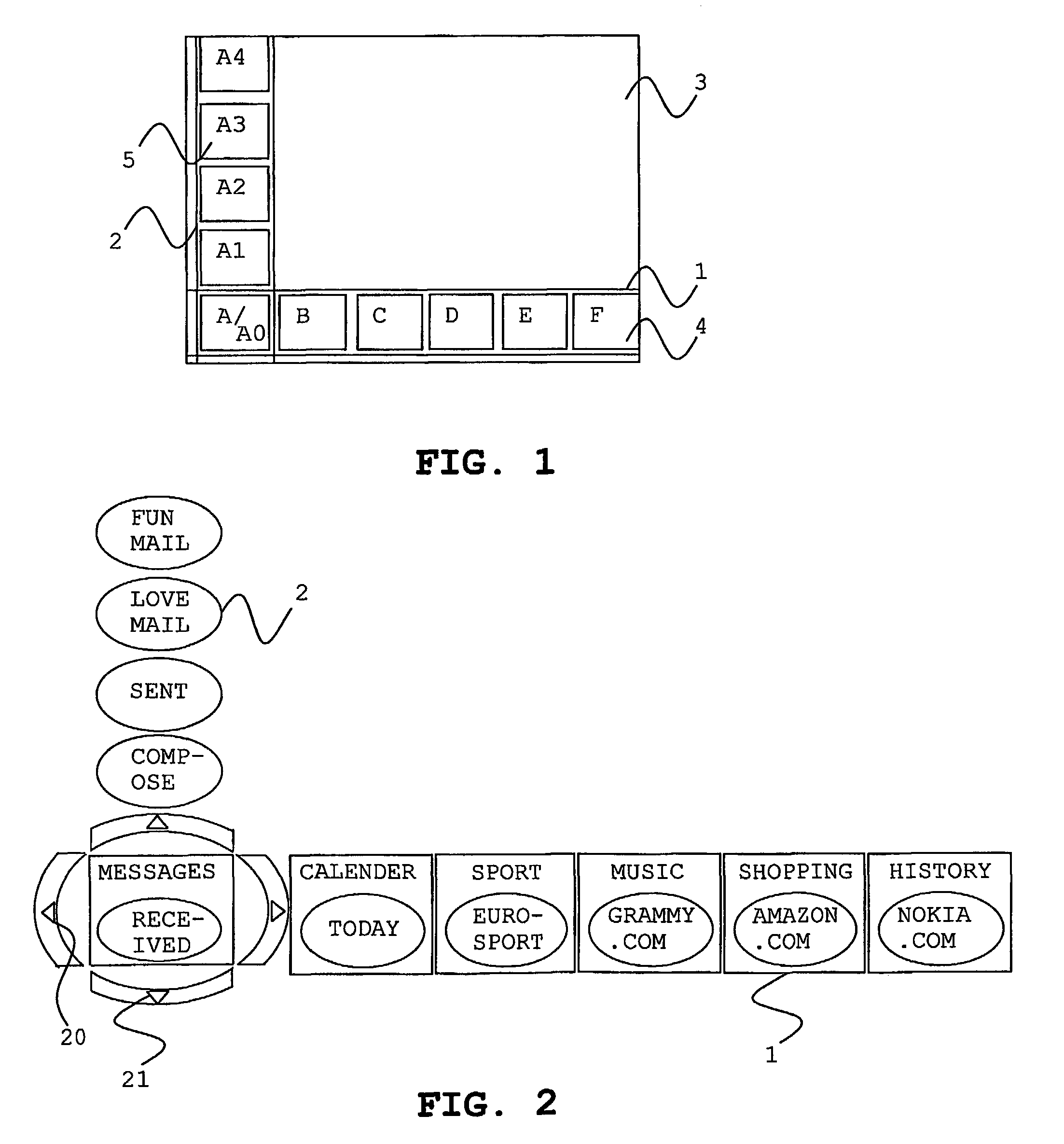
[0026]the invention will now be described with reference to FIG. 1. A first and a second intersecting bar 1, 2 are displayed on a touch screen 3. The bars are preferably displayed near the edge of the screen in order to block as little of the screen as possible. The screen may e.g. display a TV program or an Internet homepage in the background, which preferably should be presented as visually as possible. The first bar 1 displays a number of containers A, B, . . . , F containing objects. The second bar 2 displays a number of objects A0, A1, . . . , A4 contained in the container at the intersection of the bars, i.e. container A.
[0027]An object in the second bar 2 is activated by one touch on that object. This may for instance be an event such as switching TV channels, access of a homepage on the Internet, or a selection of background colour of the screen.
[0028]It is possible to allow further levels than just two: container and object. Activation of an object may display sub-objects i...
second embodiment
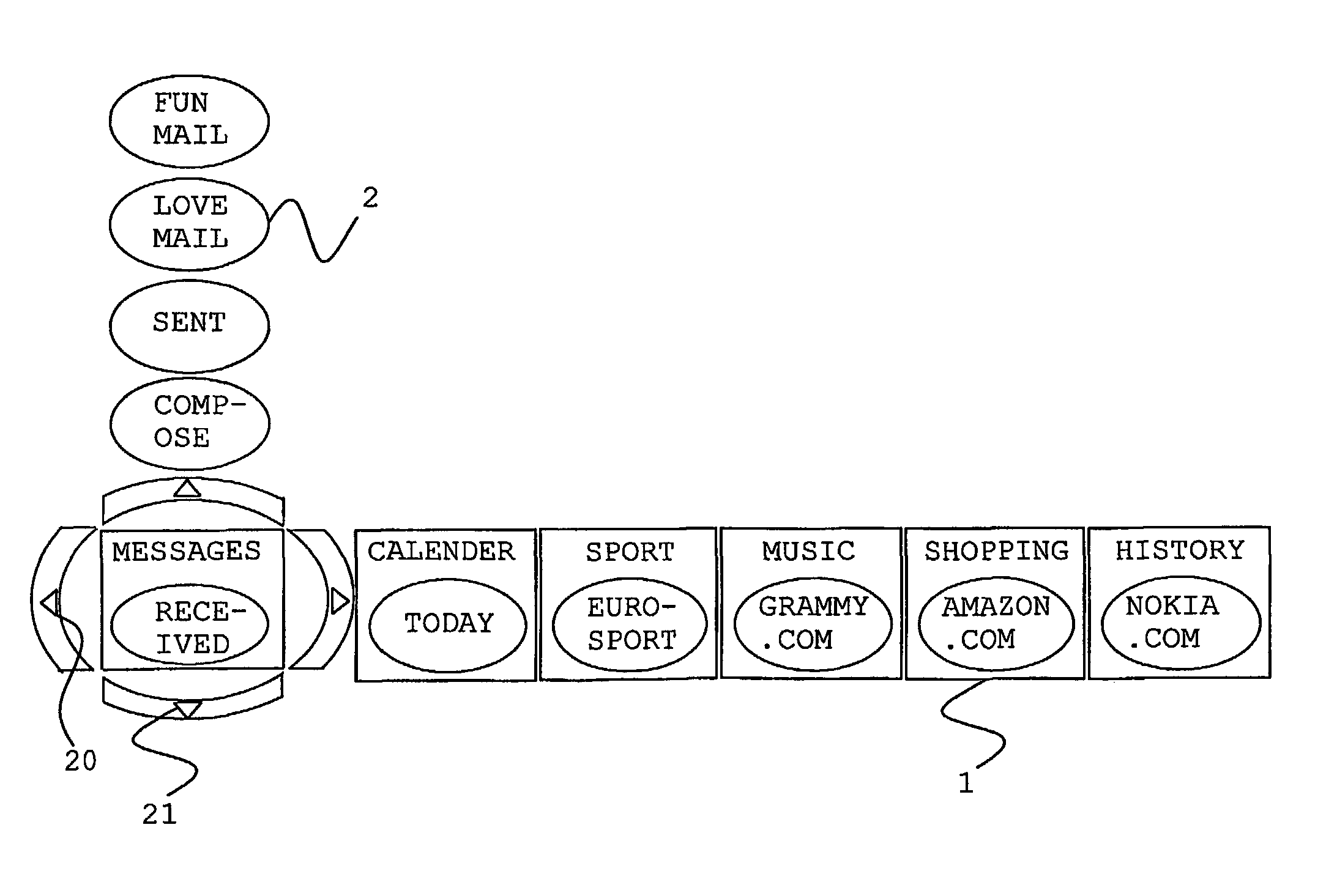
[0031]A second embodiment will now be described with reference to FIG. 2. In case there are more containers to display than there is space for on the screen, a marker, e.g. an arrow 20, is displayed at an end of the first bar 1. A touch on the marker scrolls the containers in the first bar 1, which makes it possible to select each container. Similarly, if there are more objects than there is space for on the screen, another marker 21 is displayed at an end of the second bar 2 to make it possible to scroll through the objects. It is also possible to display a marker at both ends of a bar to make it possible to scroll that bar in two directions. It is further possible to display markers at the intersection of the bars as seen in FIG. 2. It is yet further possible to display markers even when not necessary, i.e. when all containers or all objects could be shown on the screen. By showing markers even when not necessary the user recognises the look of the displayed bars, which facilitate...
third embodiment
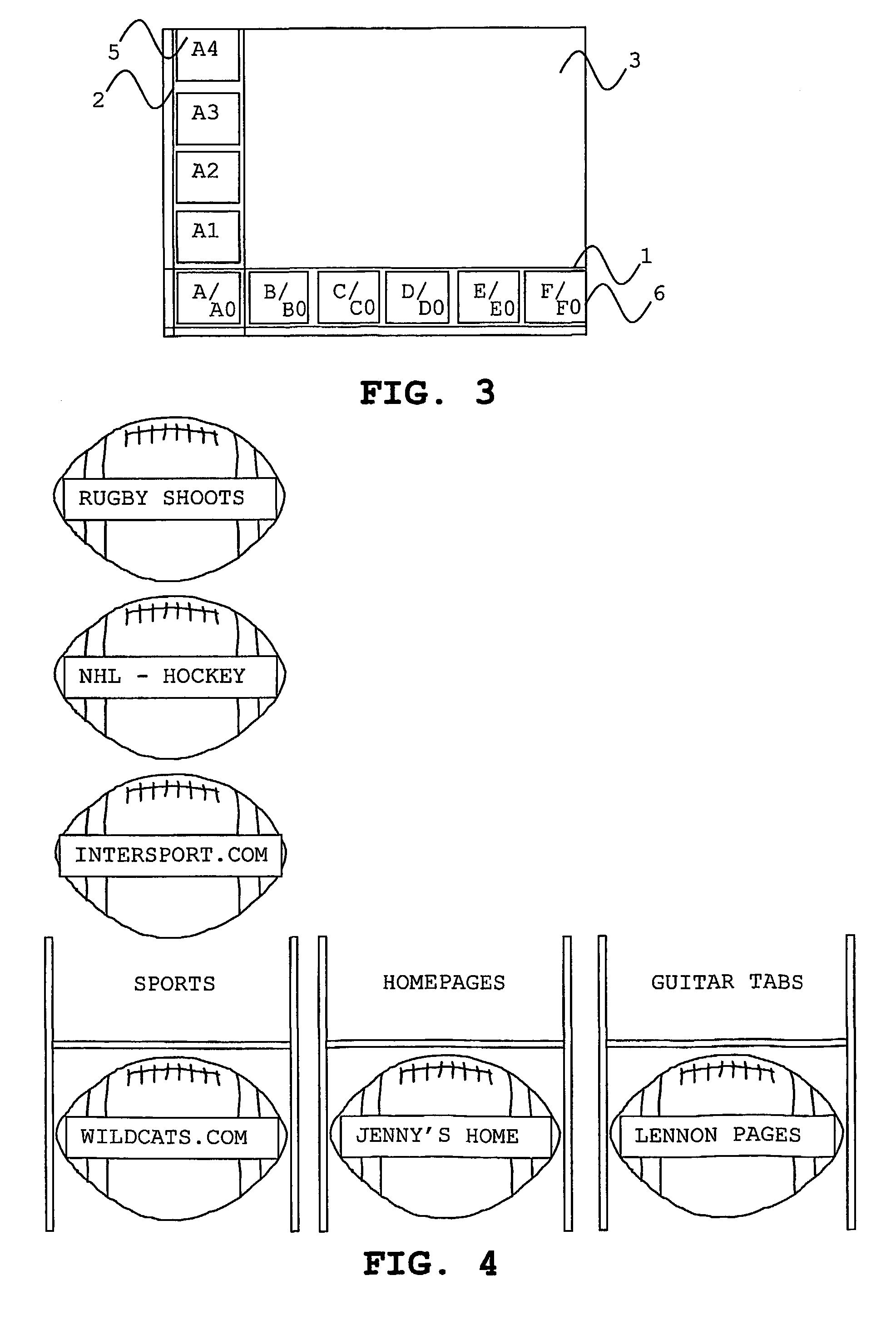
[0033]the present invention will now be described with reference to FIG. 3, wherein each container 6 in the first bar 1 displays one object directly A0, B0, . . . , F0, i.e. even when not being located in the intersection with the second bar 2. In this embodiment it is possible to activate an object A0, B0, . . . , F0 directly in the first bar 1. Each container 6 in the first bar 1 comprise two fields; one touch on an object in the respective container activates that object, preferably with a visualisation that first moves that container to the intersection of the bars and then activating the selected object; one touch on a container moves that container to the intersection of the bars, and therewith the second bar displays the objects contained in that container. The visualisation in connection with activated objects in the first bar is preferably used to make it feasible for the user to understand what has happened.
[0034]The objects displayed in the first bar may be selected in se...
PUM
 Abstract
Description
Claims
Application Information