Method of monitoring belt orientation and/or belt travel of a band belt conveyor apparatus and a band belt conveyor

a technology of a band belt conveyor and a belt conveyor, which is applied in the direction of conveyors, conveyor parts, control devices of conveyors, etc., can solve the problems of increasing the level of heat generation, the belt running inclinedly in an off-track direction, and the problem of band belts. and troubles, etc., to achieve the effect of monitoring inexpensively

Active Publication Date: 2008-04-08
ZIEGLER MANFRED DR
View PDF18 Cites 17 Cited by
  • Summary
  • Abstract
  • Description
  • Claims
  • Application Information

AI Technical Summary

Benefits of technology

[0014]An object of the present invention is to provide a method by which belt orientation and / or belt travel of a band belt conveyor apparatus can be monitored inexpensively using comparatively simple means.
[0015]Another object of the present invention is to provide a method of monitoring at least one of belt orientation and belt travel of a belt conveyor apparatus, which can provide adequately reliable and accurate measurement results without involving highly complex measuring and sensing systems.
[0016]Yet another object of the present invention is to provide a band belt conveyor apparatus for bulk material which has means of comparatively simple nature for monitoring correct setup and operation of the apparatus.
[0021]In another preferred feature, measurement of the thrust stress is effected in first and second mutually perpendicular axes, preferably for example in the direction of the belt travel and transversely with respect to the direction of belt travel, for example by means of multi-axis force sensors or thrust stress sensors. Comparison of the lengthwise and transverse force components within the belt with the loading on the belt makes it possible to ascertain the static friction between the belt and the support roller, and thus information about the tendency for the belt to run off-track or inclinedly can be derived therefrom. A drop in the coefficient of friction at one side of the belt leads to the belt running off-track or inclinedly. In the case for example of a conveyor belt apparatus operating in the open air, as in open cast mining, such a one-sided drop in the coefficient of friction could be caused for example by heavy rain or a rain storm or by the arrangement being sprayed with water. Taking account of all lengthwise and transverse forces at all support rollers in the circulatory path makes it possible to obtain information about the current risk of off-track or inclined running of the belt and affords the possibility of implementing countermeasures. It is possible for example to envisage spraying water on the side of the belt to which the belt is running off-track, in a deliberate and specifically targeted fashion to remedy the problem.
[0025]As will be seen from the description hereinafter of a preferred embodiment, that structure provides that the entire belt conveyor apparatus can be monitored over the length of an endlessly circulating belt by means of a minimum number of measuring devices, without the need for that purpose to provide measuring devices at individual rollers or at individual support roller frame structures.

Problems solved by technology

Problems with and troubles on band belts are primarily to be attributed to defective support rollers or support frame structures which are improperly oriented.
Improperly oriented support structures cause the belt to run inclinedly in an off-track condition or give rise to overloading at individual belt support rollers.
Bearing damage at the bearings of the belt support rollers are frequently the cause of problems and difficulties in that respect.
That gives rise to an increased level of heat generation which in the worst-case scenario can lead to an open fire.
Although that operating procedure has proven to be worthwhile nonetheless it relatively frequently happens that support rollers which are in a good condition are picked out for removal or replacement because the procedure does not provide absolute accuracy in terms of locating the support rollers.
It can also be easily imagined that it is a comparatively arduous task to cover what may involve hundreds of kilometers on belt lines in that way.
If the quality of alignment is somewhat worse however it is no longer possible to guarantee that the belt travels in a central position but it is not possible to detect that improper orientation of the belt by way of the procedure involving detecting sound emission.
It will be noted however that that method is also comparatively complicated and expensive.

Method used


Image

  • Method of monitoring belt orientation and/or belt travel of a band belt conveyor apparatus and a band belt conveyor
  • Method of monitoring belt orientation and/or belt travel of a band belt conveyor apparatus and a band belt conveyor
  • Method of monitoring belt orientation and/or belt travel of a band belt conveyor apparatus and a band belt conveyor

Examples


Embodiment Construction

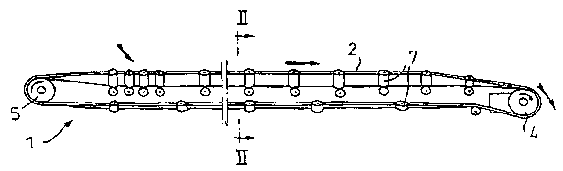
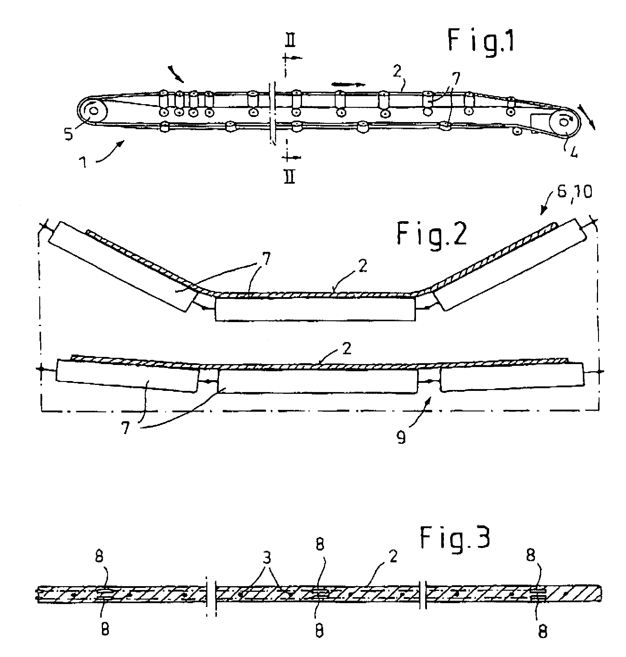
[0037]Referring firstly to FIG. 1 shown therein in diagrammatically simplified form is a typical band belt conveyor 1 comprising an endlessly circulating band belt 2 of rubber-elastic material with tensile carriers in the form of steel cables or wires 3 which are vulcanised therein, a drive station including a drive drum 4 and a rear station comprising a rear drum 5. Reference numeral 6 denotes support roller frame structures which are arranged between the drive drum 4 and the rear drum 5 and which include support rollers 7 on which the belt 2 is supported at spaced intervals between the drums 4 and 5. It will be appreciated that instead of support roller frame structures 6 it is also possible to provide support roller garland portions. It will be appreciated that belt tensioning devices and belt slide members are not illustrated here for reasons of simplification of the drawing. It will thus be fully appreciated that the belt conveyor 1 shown in FIG. 1 is only illustrated in a high...


PUM


Abstract

A method of monitoring belt orientation and / or belt travel of a belt conveyor apparatus includes measurement of compression and / or thrust stress patterns within the belt as it passes over a support roller arrangement by measuring means embedded in the belt. The measured signal is recorded and associated with a specific support roller. The signal pattern allows conclusions to be drawn about misalignments of the belt or possible defects in the support rollers. A belt conveyor apparatus has measuring means embedded in the belt and including at least one multi-axis sensor for detecting the stress variations in the belt.

Description

CROSS-REFERENCES TO RELATED APPLICATIONS[0001]This application claims the priority of German patent application Serial No 10 2005 021 627.7 filed May 6, 2005, the subject-matter of which is incorporated herein by reference.FIELD OF THE INVENTION[0002]The invention concerns a method of monitoring belt orientation and / or belt travel of a band belt conveyor apparatus.[0003]The invention further concerns a band belt conveyor for bulk material.[0004]It will be noted here that the reference to belt travel in accordance with the present invention is used to include in particular also the detection of defective support rollers within the belt conveyor apparatus.BACKGROUND OF THE INVENTION[0005]A fairly typical form of band belt conveyor apparatus using for example a webbing belt or a rubber belt or a belt of like material includes at least one flexible band belt such as of webbing or rubber material which circulates endlessly between reversal stations and / or drive stations. The belt forms a...

Claims


Application Information

Patent Timeline
Patent Type & Authority Patents(United States)
IPC IPC(8): B65G43/00
CPCB65G15/08B65G43/02B65G2203/0275B65G2203/042
Inventor ZIEGLER, MANFRED
Owner ZIEGLER MANFRED DR
Why Eureka
Try Eureka