

Sensor unit with fastening element for fastening to a structure
a sensor unit and fastening element technology, applied in the direction of optical apparatus testing, instruments, roads, etc., can solve the problems of considerable energy input, inconvenient fastening of sensors, and ultimately a great deal of logistical effor
Pending Publication Date: 2022-09-22
THALES MANAGEMENT & SERVICES DEUT GMBH
View PDF0 Cites 0 Cited by
- Summary
- Abstract
- Description
- Claims
- Application Information
AI Technical Summary
Benefits of technology
The technical effect of this patent is to provide an inexpensive fastening element and sensor unit that can be easily attached to a structure for monitoring.
Problems solved by technology
Although elastic adhesives have a high resistance to weathering and aging, they also compensate for expansion and movement of the structure and are therefore not suitable for fastening sensors which are intended to measure forces acting on the structure.
However, this requires a considerable energy input in the form of heat, which, in addition to the high energy costs, requires equipment that makes it possible to provide the required energy even in remote and difficult-to-access track sections.
The heavy and bulky equipment required for inductive heating has to be transported to the place of use by the trained specialists, which ultimately entails a great deal of logistical effort.
Using this method, however, the heat input for curing the adhesive only takes place at points.
Method used
View moreImage
Smart ImageViewing Examples

Examples
first embodiment
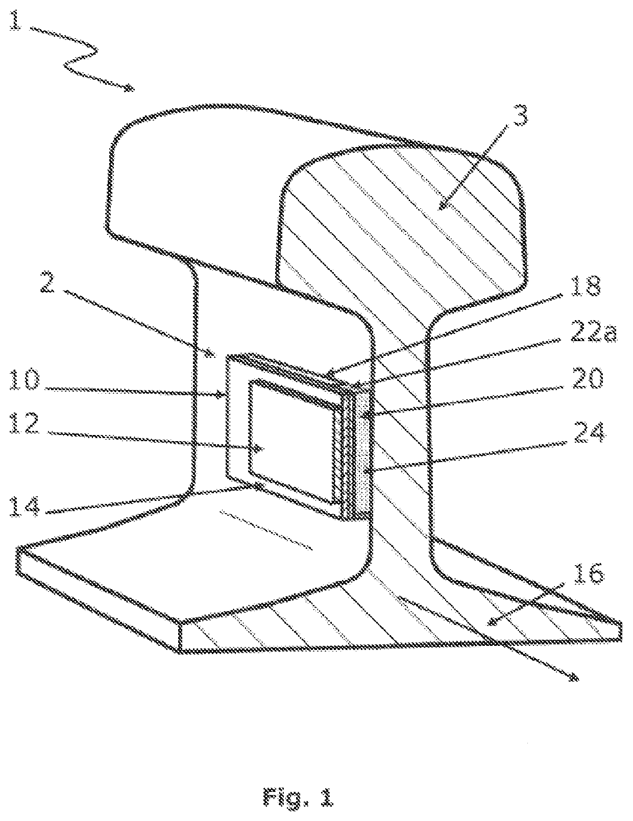
[0043]FIG. 1 shows a sensor arrangement having a sensor unit and a structure to be monitored in a sectional view;
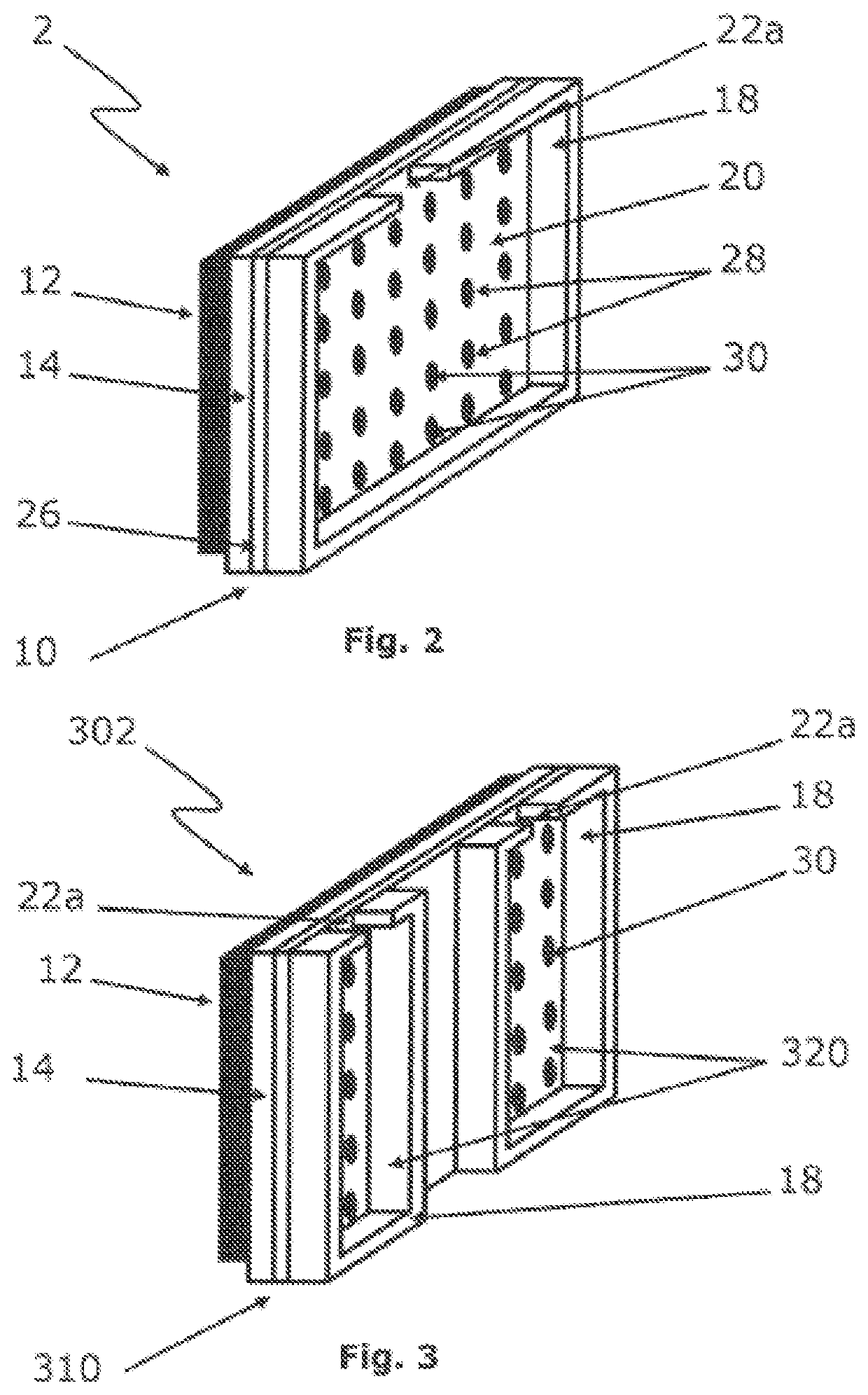
[0044]FIG. 2 shows the first embodiment of a sensor unit from FIG. 1 in a perspective view, the fastening element having a single cavity;
second embodiment
[0045]FIG. 3 shows a sensor unit in a perspective view, the fastening element having two cavities;
third embodiment
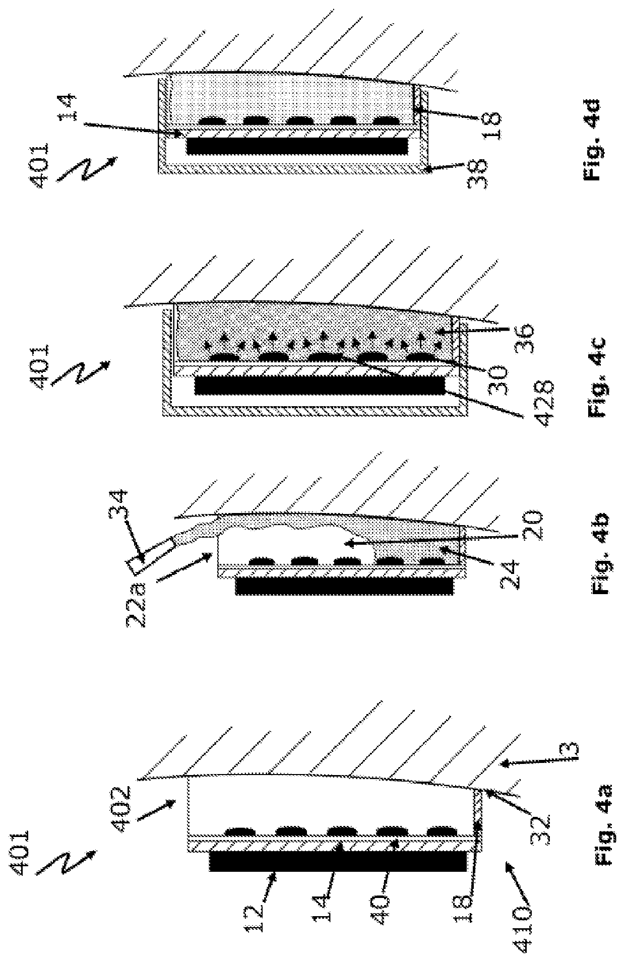
[0046]FIG. 4a-d show the various method steps of a method according to the invention for fastening a sensor arrangement having a sensor unit in a sectional view, the fastening element comprising a cavity and a passage recess on the frame side;
Login to View More PUM
| Property | Measurement | Unit |
|---|---|---|
| Electrical conductor | aaaaa | aaaaa |
| Transparency | aaaaa | aaaaa |
| Distance | aaaaa | aaaaa |
Abstract
A fastening element for a sensor is disclosed, which fastening element can be fastened to a structure by means of a light-curing adhesive. The light-curing adhesive is cured within the cavities provided for receiving the light-curing adhesive by direct and / or indirect illumination. Furthermore, a sensor unit having a sensor and a fastening element, an arrangement having a sensor unit and a structure, and a method for providing an arrangement is disclosed.
Description
CROSS-REFERENCE TO RELATED APPLICATIONS[0001]This continuation application claims priority to PCT / EP2020 / 085779 filed on Dec. 11, 2020 which has published as WO 2021 / 116417 A1 and also the European application number 19215774.1 filed on Dec. 12, 2019 and European application number 20152514.4 filed on Jan. 17, 2020, the entire contents of which are fully incorporated herein with these references.DESCRIPTIONField of the Invention[0002]The invention relates to a fastening element for fastening a sensor to a structure to be monitored, in particular a rail, to a sensor unit having such a fastening element, to a sensor arrangement for fastening the sensor unit to a structure to be monitored, and to a method for arranging the sensor unit.Background of the Invention[0003]Fastening elements, which are fastened by means of adhesive substances, are already known from the prior art and are used to attach components, in particular sensors, to structures. A typical field of application for this ...
Claims
Login to View More Application Information
Patent Timeline
 IPC IPC(8): G01D11/30B29C65/14G01D21/02B61K9/08
CPCG01D11/30B29C65/1406G01D21/02B61K9/08G01L1/242B61L1/02B61L1/06B61L1/163B61L1/166E01B26/00G01D5/35316G01D5/35374G01L1/246G01M5/0025G01M5/0058G01M11/085G01L1/26G01B11/16
InventorBREITWEG, ROLF
OwnerTHALES MANAGEMENT & SERVICES DEUT GMBH