Circuit arrangement and data processing method

a data processing method and circuit technology, applied in the direction of testing circuits, instruments, nuclear elements, etc., can solve the problems of aforementioned tolerance limit definition becoming even more difficult, and the case is not the case, so as to prevent the manipulation of input signals by hackers

Inactive Publication Date: 2006-09-05
INFINEON TECH AG
View PDF11 Cites 0 Cited by
  • Summary
  • Abstract
  • Description
  • Claims
  • Application Information

AI Technical Summary

Benefits of technology

[0009]An advantage of the inventive circuit arrangement or of the inventive data processing method in this case is that interfering parameters are identified not by ascertaining the physical magnitudes of the parameters, but rather by the effect thereof. Another advantage is that this means that the effect of the parameters delivers the result, and not sensors placed at the edge of the electronic circuit. The environmental influences on the circuit can thus also be monitored less expensively and more reliably than was previously the case.
[0014]If even the input signal is now intended to be unfore seeable for a potential hacker, then suitable means, such as a random number generator, can be used to alter the input signal specifically. The result of this is that not only interfering parameters on the circuit itself but also manipulation of the input signal by an hacker can be prevented.

Problems solved by technology

Unfortunately, this is not the case in practice.
One problem found in this context is the definition of the tolerance limits for the aforementioned parameters.
Should the combined effective tolerances of various parameters need to be taken into account, it becomes even more difficult.
Making circuits entirely insensitive to interfering influences is associated with an extremely high level of cost or is technically infeasible or is not at all possible physically.
This property of electronic circuits is utilized maliciously by hackers who wish to influence the output signals from the circuit consciously and who deliberately bring about faults.
To bring about a state for smart cards which ensures the greatest possible security, simply placing a tight restriction on the operating conditions is not a satisfactory solution.
One difficulty found in this context is defining the tolerated range.
In addition, the sensors for, by way of example, light, temperature, voltage and clock frequency cannot detect the environmental conditions directly on or in the circuit, since they are normally implemented so as to be physically isolated from the circuit which is to be monitored.
This means that the measured result delivered by the sensors does not reflect the environmental and operating conditions which are effective directly in the circuit.

Method used


Image

  • Circuit arrangement and data processing method
  • Circuit arrangement and data processing method

Examples


Embodiment Construction

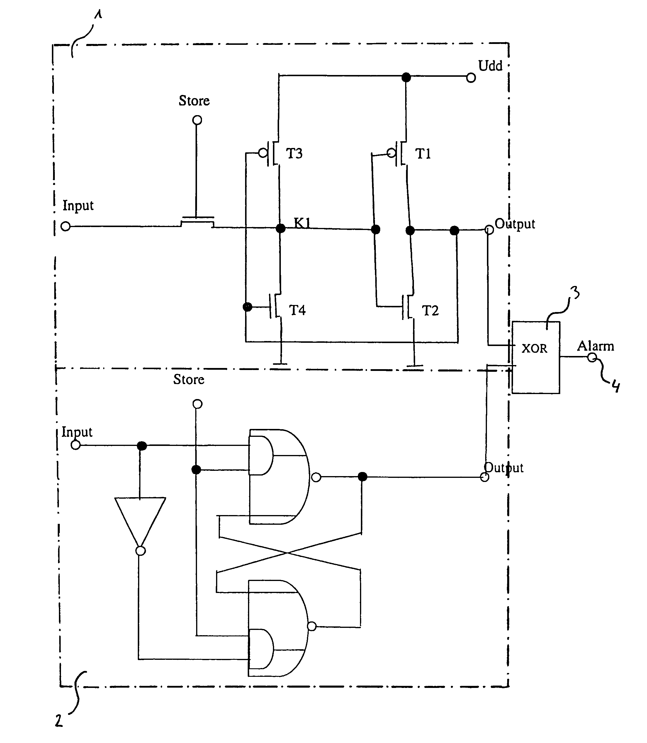
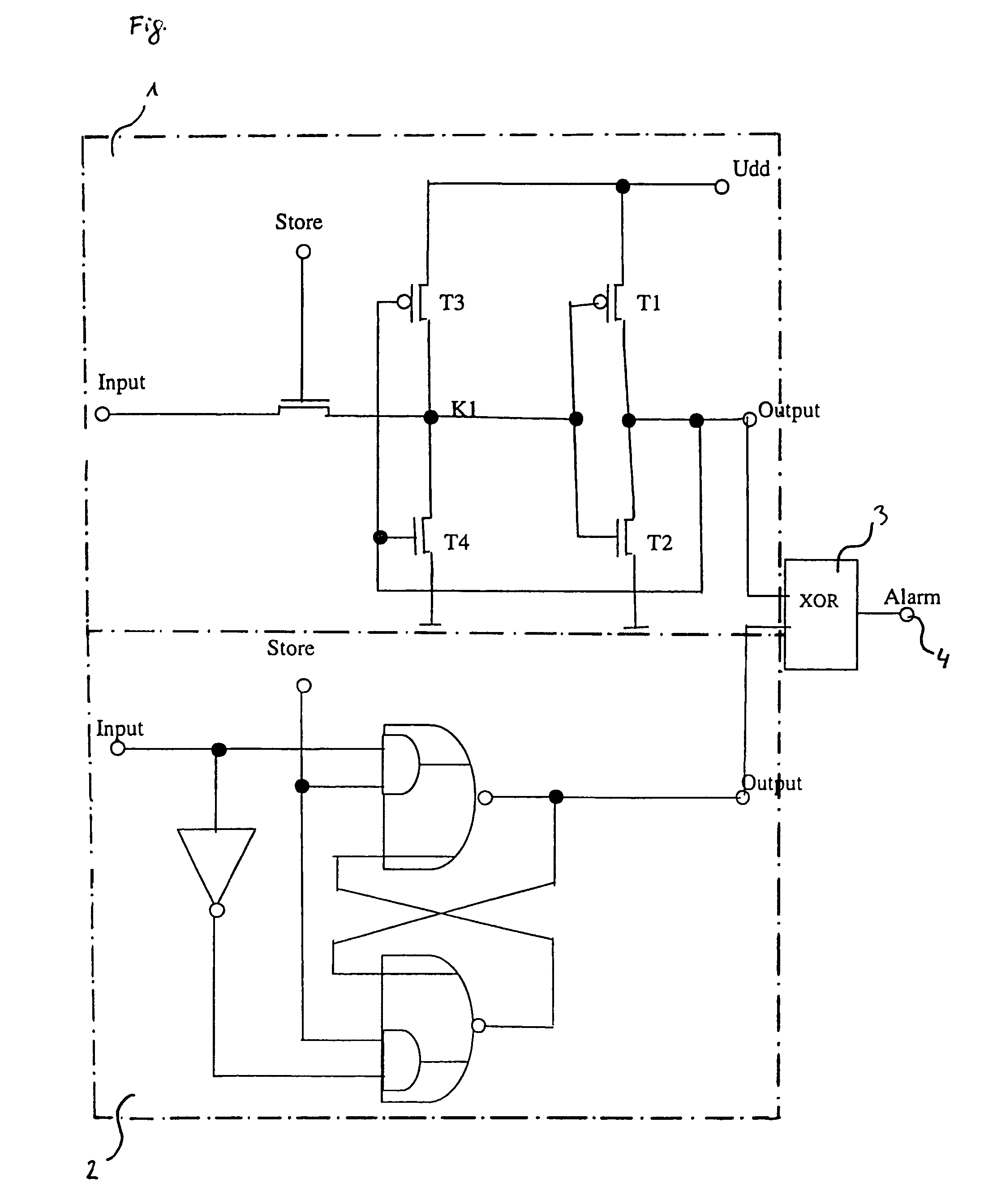
[0016]The drawing shows a latch (1) and a storage element (2). The storage element (2) is constructed from a failsafe flip flop (2). The latch (1) comprises the transistors T1, T2, T3 and T4. T1 and T2 are field effect transistors of normal design. The transistors T3 and T4 are designed to have a very high impedance. This allows this latch to be “overridden” when storing the information. This means that T3 and T4 switch distinctly after T1 and T2. This high-impedance design of the transistors T3 and T4 means that the node K1 is also susceptible to interference, since it cannot follow possible alterations quickly enough or can be discharged as a result of environmental influences, for example, such as light or temperature. Acting in parallel with the latch (1) is a failsafe flip flop (2). The inputs on both circuits have the same signal applied to them. The outputs from the latch (1) and from the failsafe flip flop (2) are compared in a comparative circuit, an XOR gate (3). If the ou...


PUM


Abstract

A circuit arrangement in which two parallel subcircuits having a same functionality have a same input signal applied to them, and their output signals are compared in a common comparison arrangement. The two subcircuits are designed differently in terms of sensitivity to changes in environmental or operating parameters. Impermissible environmental parameters are indicated if the output signals differ from one another, and an alarm is generated.

Description

CROSS-REFERENCE TO RELATED APPLICATION[0001]This application is a continuation of International Patent Application Serial No. PCT / DE02 / 04443, filed Dec. 4, 2002, which published in German on Jul. 3, 2003 as WO 03 / 054789, and is incorporated herein by reference in its entirety.FIELD OF THE INVENTION[0002]The invention relates to a circuit arrangement and to a data processing method which can be operated therewith in which two parallel subcircuits having the same functionality have the same input signal applied to them, and their output signals are compared in a common comparison arrangement.BACKGROUND OF THE INVENTION[0003]Ideally, electronic circuits are insensitive to interfering influences such as fluctuations in the supply voltage [lacuna] in the clock frequency or environmental influences such as light and temperature. Unfortunately, this is not the case in practice. Thus, every electronic circuit operates without error only in a particular tolerance range for said parameters. O...

Claims


Application Information

Patent Timeline
Patent Type & Authority Patents(United States)
IPC IPC(8): G06F1/24G06K19/073
CPCG06K19/07372G06K19/073
Inventor POCKRANDT, WOLFGANG
Owner INFINEON TECH AG
Why Eureka
Try Eureka