Multiple optical fiber tap device and methods of use thereof

a technology of optical fiber and optical fiber tap, which is applied in the field of optical fiber tap devices and systems, can solve the problems of affecting analog telemetry optical systems, reducing the output or emitted power of light sources, and affecting the quality of optical systems, etc., and achieves the effects of small physical packages, inexpensive monitoring, and robustness

Active Publication Date: 2020-08-18
MICATU
View PDF30 Cites 0 Cited by
  • Summary
  • Abstract
  • Description
  • Claims
  • Application Information

AI Technical Summary

Benefits of technology

[0012]Advantages of the device of the present technology include the potential for the device to have a small physical package, which allows optical power to be inexpensively monitored in a closed loop control system. The optical tap device of the present technology advantageously provides an inexpensive and robust solution that minimizes space requirements for the optical tap. An additional advantage of the present technology is that the main fiber is configured to be aligned with the center axis with the light source. As a result, there is no impairment or loss of coupling power to the main fiber. The tap fiber lies radial relative to the center axis and is located one fiber pitch away such that it collects a known portion of the emitted Gaussian optical power, in this example 2% nominal. This is done with no loss in coupled power to the main fiber. The tapped light is then converted to an electrical signal via a photodiode and a transimpedance amplifier and used as an input to a feedback control system.

Problems solved by technology

Light sources, such as light emitting diodes (LEDs) and incandescent lamps among others, suffer degradation over time.
The degradation causes a decrease in the output or emitted power of the light source, which negatively impacts analog telemetry optical systems where control of the emitted power is critical in order to provide stable and accurate measurements.
Producing such optical taps requires a relatively large physical device, pricey components, and expensive capital equipment, or a combination of these.
Such an optical tap incurs a penalty in the form of reduction of transmitted power.
Some power is diverted to the monitor photodetector and some is lost by device coupling imperfections.
The device is complex, requiring a first light beam to pass through a first port and fiber.
Limitations to existing optical taps include their complexity, size, and cost.
In addition, to facilitate tap pickoff many of these methods impair the main light transmission path by beam splitting, resulting in a signal loss.

Method used


Image

  • Multiple optical fiber tap device and methods of use thereof
  • Multiple optical fiber tap device and methods of use thereof
  • Multiple optical fiber tap device and methods of use thereof

Examples


example

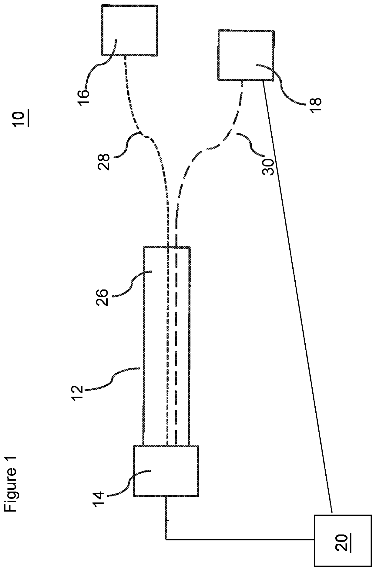
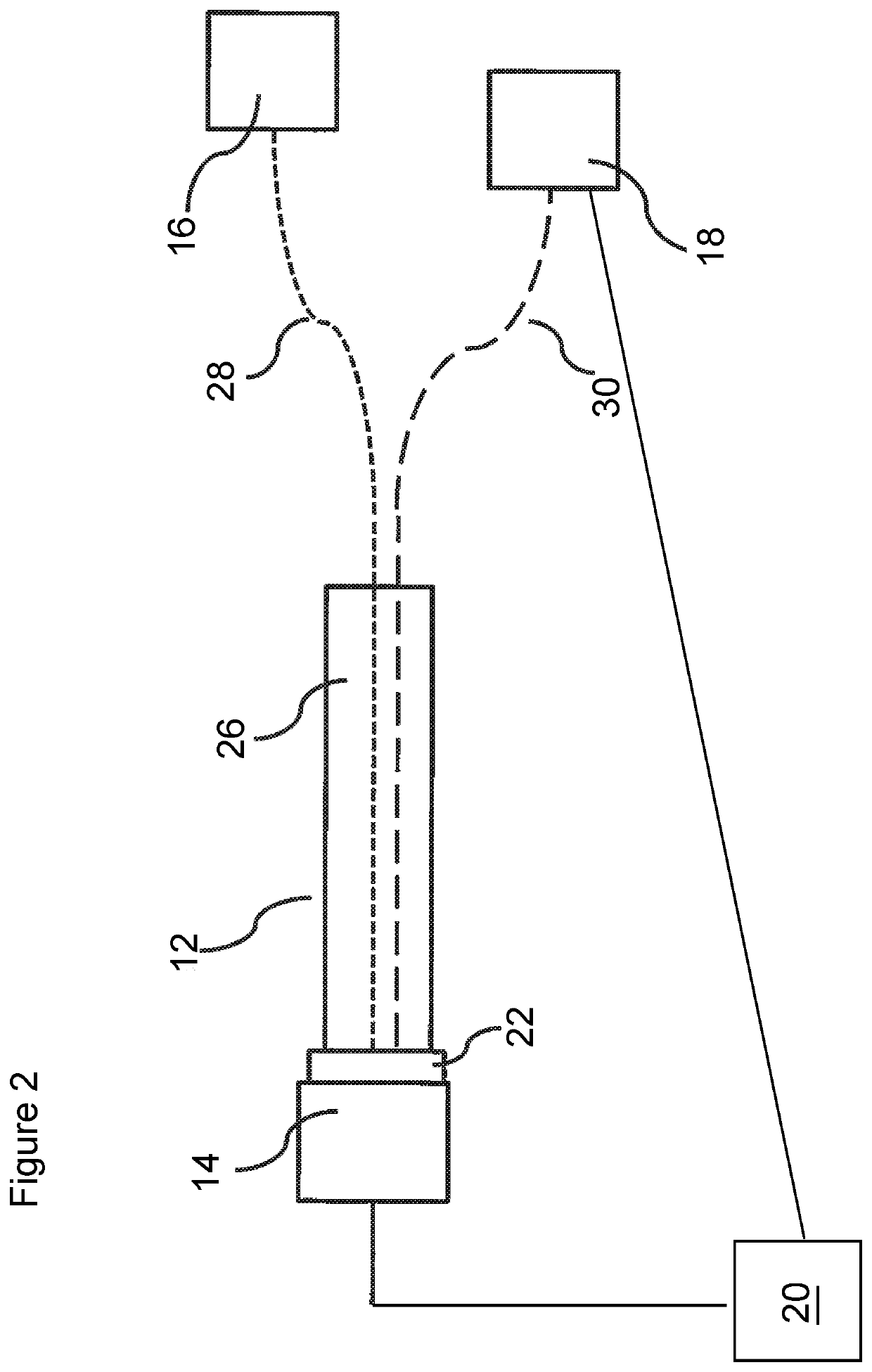
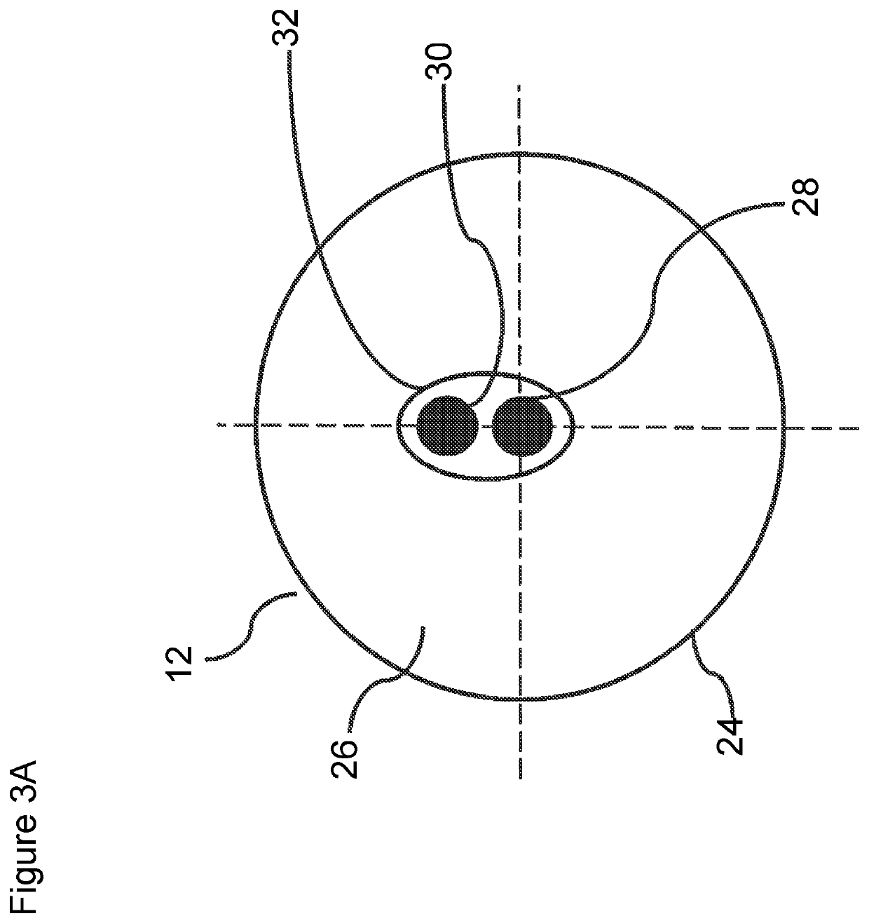
[0042]An optical tap was constructed by placing two 200 uM silica fibers into a 500 uM groove of a 3D printed clamshell-like ferrule, such that 0.5 mm of fiber protruded from the end of the ferrule. The clamshell ferrule was folded and the fibers were glued in place using adhesive. The fibers and an LED were placed into a 15-mm stainless steel tube with an inner diameter of 4.63 mm. The LED and the fibers were aligned within the tube by adjusting the depth of the fibers and by rotating the LED within the stainless-steel tube. After adjusting, the power was peaked on the main emitter fiber so that output power was 550 uW, and the power on the tap fiber was measured to be 16 uW, or 2.9% of the main emitter fiber power.

[0043]Experimental Procedure

[0044]An optical tap was constructed by placing two 200 uM silica fibers into a 500 uM groove of a 3D printed clamshell-like ferrule, such that 0.5 mm of fiber protruded from the end of the ferrule. The clamshell ferrule was folded and the fib...


PUM

PropertyMeasurementUnit
inner diameteraaaaaaaaaa
lengthaaaaaaaaaa
shapeaaaaaaaaaa

Abstract

The present invention relates to an optical tap device. The optical tap device includes a cylinder having a rigid outer surface. A ferrule is configured to be located within the outer surface of the cylinder. The ferrule includes an inner chamber extending along a length of the ferrule. An emitter fiber and at least one tap fiber are located within the inner chamber. The emitter fiber is positioned within the inner chamber to be located at a central axis of a light source abutting the ferrule and the at least one tap fiber is positioned within the inner chamber to be located radial to the central axis of the light source abutting the ferrule. An optical feedback system and a method of providing optical feedback are also disclosed.

Description

[0001]This application claims the benefit of U.S. Provisional Patent Application Ser. No. 62 / 504,820 filed May 11, 2017, which is hereby incorporated by reference in its entirety.FIELD OF THE INVENTION[0002]The present invention pertains to the field of optical devices, and more specifically, to a multiple optical fiber tap device, system, and methods of use thereof.BACKGROUND OF THE INVENTION[0003]Light sources, such as light emitting diodes (LEDs) and incandescent lamps among others, suffer degradation over time. The degradation causes a decrease in the output or emitted power of the light source, which negatively impacts analog telemetry optical systems where control of the emitted power is critical in order to provide stable and accurate measurements. Optical taps can be used to split a portion of output light and send it to a detector, such that light output can be monitored and compensated.[0004]Existing optical taps make use of several techniques, including free space optics,...

Claims


Application Information

Patent Timeline
Patent Type & Authority Patents(United States)
IPC IPC(8): G02B6/42G02B6/28G02B6/38
CPCG02B6/4286G02B6/4221G02B6/385G02B6/4204G02B6/2852G02B6/3885
Inventor KENNEDY, JAMESSTELICK, SCOTTWALKER, KRISPRADHAN, ATUL
Owner MICATU
Why Eureka
Try Eureka