DC adapter and electronic apparatus using the same

a technology of dc adapter and electronic apparatus, applied in the direction of cell components, coupling device connections, instruments, etc., can solve the problems of affecting the operation of the electronic apparatus, the insertion of the battery may rattle within the housing portion, and the electrical apparatus does not, so as to achieve smooth insertion into the battery housing portion, prevent wrong insertion, and stable insertion

Inactive Publication Date: 2008-04-08
SONY CORP
View PDF17 Cites 23 Cited by
  • Summary
  • Abstract
  • Description
  • Claims
  • Application Information

AI Technical Summary

Benefits of technology

[0010]An object of the present invention is to provide a DC adapter and an electronic apparatus using the DC adapter, in which wrong insertion of the DC adapter that is configured to be housed in the battery housing portion for primary and secondary batteries can be prevented, and positional regulation in the battery housing portion is accurately established for the primary and secondary batteries so that the batteries can be housed in the battery housing portion in a stable condition.
[0011]Another object of the present invention is to provide a DC adapter and an electronic apparatus using the DC adapter, in which even when a DC adapter is inserted into the apparatuses other than its conforming apparatus, safety of the apparatuses can be ensured.
[0014]According to the DC adapter and electronic apparatus using the DC adapter, when the DC adapter is housed in the battery housing portion, the insertion of the DC adapter is guided by the insertion guide portion having a shape corresponding to that of the insertion limiting portion of the DC adapter. As a result, the DC adapter can be inserted into the battery housing portion smoothly. When the DC adapter is inserted into the battery housing portion with the reversed polarity, the insertion limiting portion comes into contact with the side wall formed in the battery housing portion with the result that the insertion of the DC adapter is limited. As a result, wrong insertion can be prevented. Further, even when a size AA dry battery or secondary battery is inserted into the battery housing portion, the inner circumferential wall can also support a part of the side wall of the above battery on the insertion guide portion side, and they have their positions regulated in the cutting direction of the insertion guide portion to realize stable insertion.

Problems solved by technology

Thus, if the DC adapter is inserted into the battery housing portion with the polarity thereof wrongly set, the electronic apparatus does not operate, or any trouble related to the operation of the apparatus may be caused.
As a result, however, when the primary or secondary battery, or assembled battery obtained by arranging the secondary batteries are inserted into the battery housing portion having the above configuration, the inserted battery may rattle within the housing portion.
In this case, when the DC adapter is used in the apparatuses other than its conforming apparatus, there is a possibility that the operating voltage may differ from that of the primary or secondary battery, so that it is impossible to ensure safety of the electronic apparatus, in some cases.

Method used


Image

  • DC adapter and electronic apparatus using the same
  • DC adapter and electronic apparatus using the same
  • DC adapter and electronic apparatus using the same

Examples


Embodiment Construction

[0034]A digital still camera to which a DC adapter and an electronic apparatus according to the present invention are applied will be described below in detail with reference to the accompanying drawings.

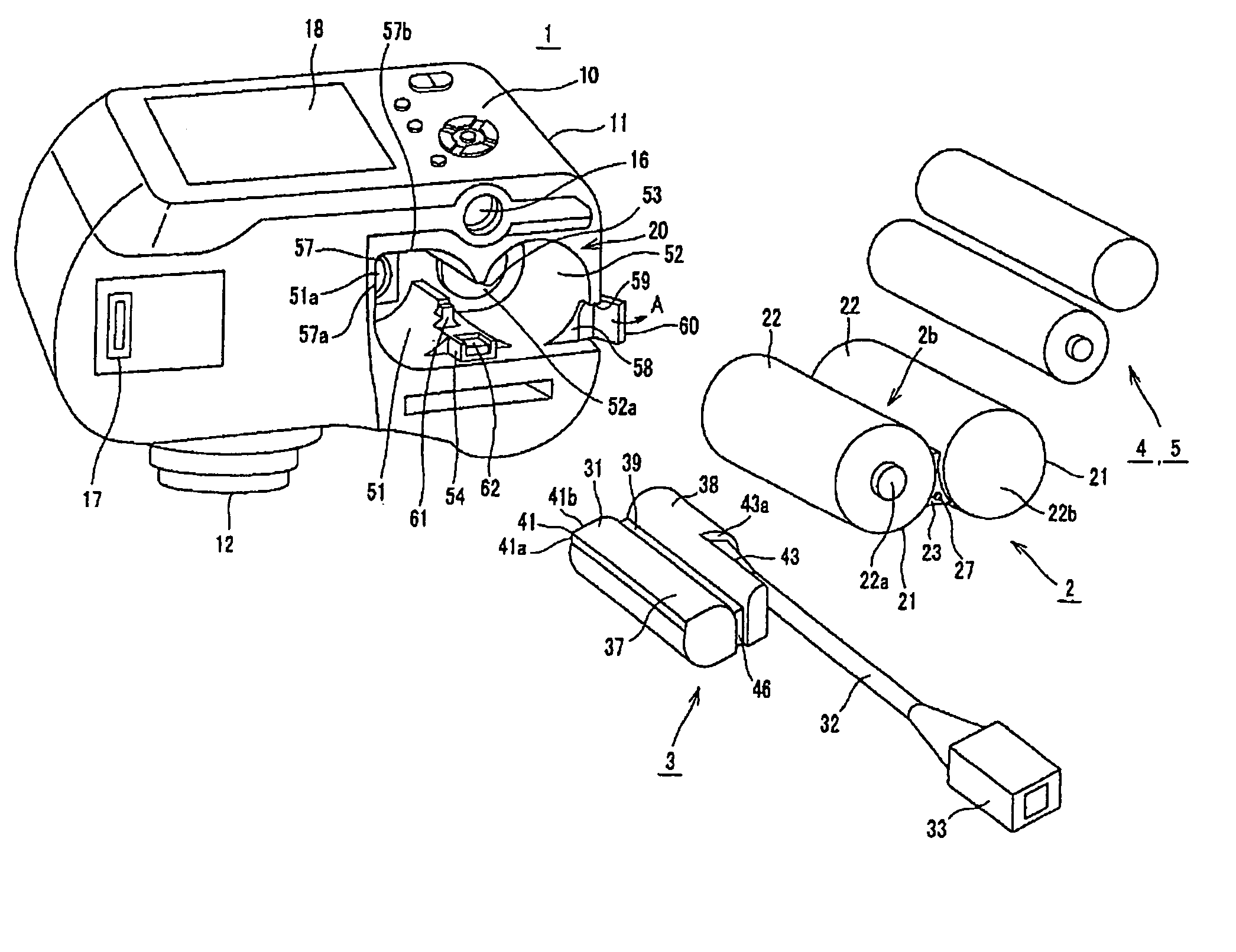
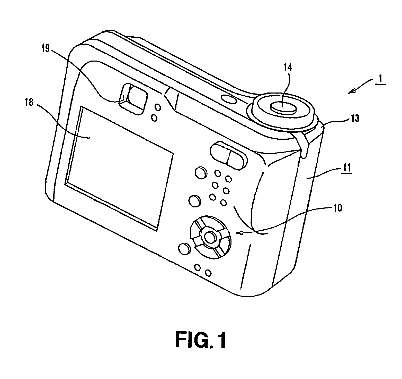
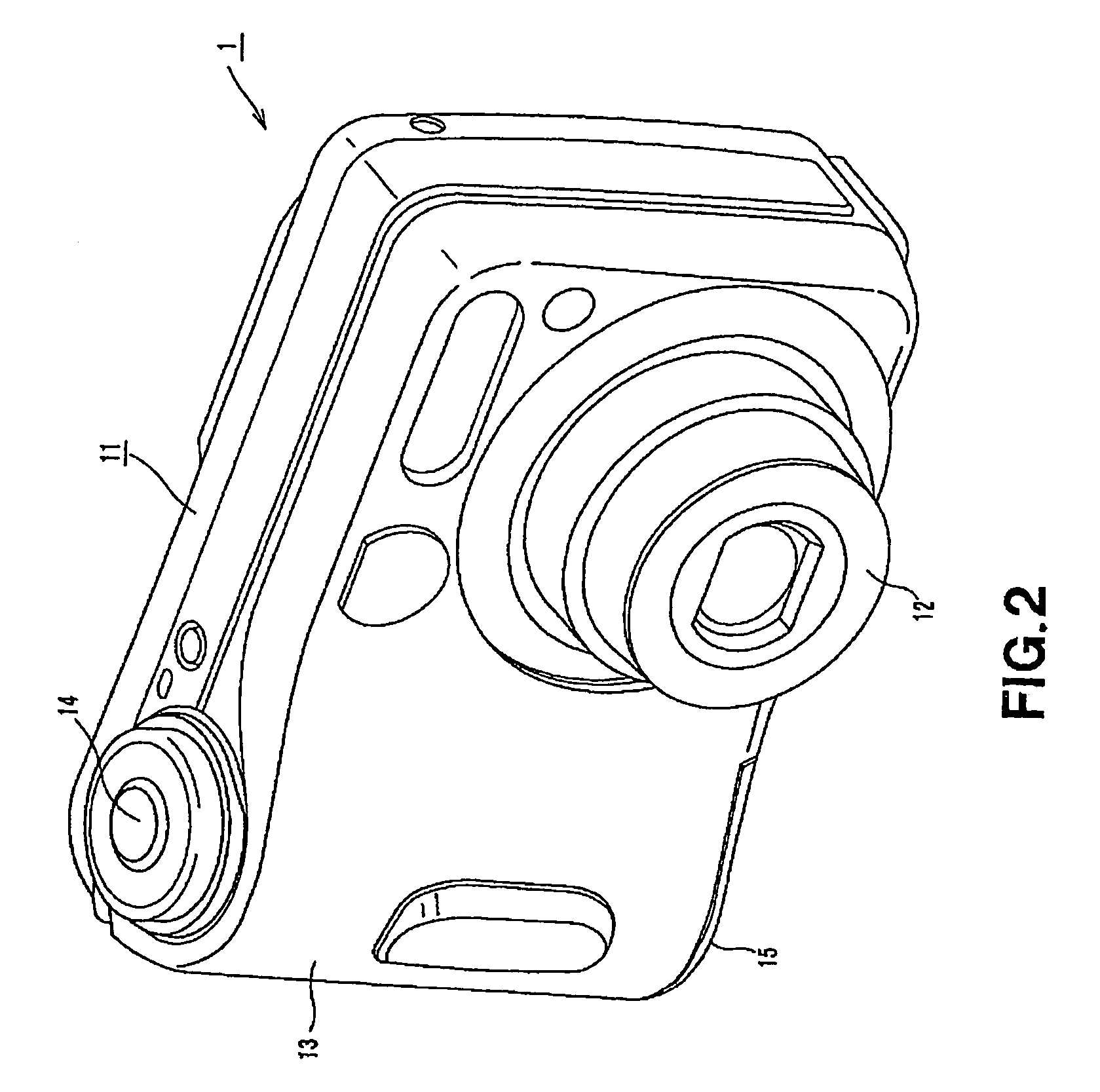
[0035]A digital still camera 1 to which the present invention is applied has a camera main body 11 as shown in FIGS. 1 to 3. The camera main body 11 has a lens portion 12 constituted by a lens barrel housing a plurality of lenses on one side of the front surface thereof and has a grip portion 13 which is gripped by a user on the other side of the front surface thereof. The grip portion 13 is so formed as to blow up from the front surface of the camera main body 11 so that the grip portion 13 can be stably gripped by a hand and fingers, as shown in FIGS. 2 and 3. The camera main body 11 also has a shutter button 14 on the grip portion 13 side of the upper surface.

[0036]Formed within the grip portion 13 is a battery housing portion 20 (shown in FIG. 9) which houses a primary battery s...


PUM

PropertyMeasurementUnit
center angleaaaaaaaaaa
charge-dischargeaaaaaaaaaa
center angle θ1aaaaaaaaaa

Abstract

A DC adapter that can be housed in a battery housing portion of an electronic apparatus selectively with a primary and secondary battery. The DC adapter is connected to an AC / DC converter and is inserted into a battery housing portion of an electronic apparatus so as to supply the electronic apparatus with a DC power, wherein a substantially cylindrical adapter main body has an insertion limiting portion which is guided by an insertion guide portion of the battery housing portion when the DC adapter is inserted into the battery housing portion with the proper polarity, and comes into contact with the contact portion of the battery housing portion when the DC adapter is inserted into the battery housing portion with the reversed polarity so as to limit the insertion of the DC adapter. The insertion limiting portion is formed by projecting a part of the outer circumference of the cylindrical adapter main body in a rectangular manner along the longitudinal direction of the main body and has two sides each of which extends from a part of the outer circumference of the DC adapter. The center angle of the circular arc obtained by connecting the proximal ends of the two sides on the outer circumference of the DC adapter is less than 90°.

Description

TECHNICAL FIELD[0001]The present invention relates to a DC adapter for supplying an electronic apparatus that uses a dry battery as a power source with an external DC power and an electronic apparatus using the DC adapter.[0002]This application is based upon and claims the benefit of priority from the prior Japanese Patent Applications Nos. 2004-148501, filed May 19, 2004 and 2004-378329, filed Dec. 27, 2004, the entire contents of which are incorporated herein by reference.BACKGROUND ART[0003]Conventionally, an electronic apparatus that uses primary and secondary batteries as a power source has widely been used. The electronic apparatus of this type has a battery housing portion into which the primary battery or secondary battery is inserted. From the battery housed in the battery housing portion, a power is supplied to the apparatus and thereby the electronic apparatus is driven. By putting the secondary battery for use in the electronic apparatus in a dedicated battery charger, i...

Claims


Application Information

Patent Timeline
Patent Type & Authority Patents(United States)
IPC IPC(8): H01R3/00H01M2/10H01M2/34H02M1/10H02M3/00
CPCH01M2/342H02M1/10H02J7/0045Y02E60/10H01M50/597H02M3/02H01M50/20
Inventor NOGUCHI, TAKAYUKIIOHARA, MASUMIOKUMURA, YURIMIYAJIMA, YOICHIABE, HIDEAKI
Owner SONY CORP
Why Eureka
Try Eureka