Chromatic dispersion compensating fiber

a technology of fiber optical transmission and chromatic dispersion, which is applied in the field of optical fiber transmission, can solve the problems of reducing the error rate at the receiver, ssmf induces high losses with respect to the quantity of dispersion produced, and the profile is slightly different, so as to improve the fom value and limit the bending and micro-bending losses

Active Publication Date: 2008-04-08
DRAKA COMTEQ BV
View PDF12 Cites 181 Cited by
  • Summary
  • Abstract
  • Description
  • Claims
  • Application Information

AI Technical Summary

Benefits of technology

[0021]There is, therefore, a need for a positive chromatic dispersion compensating fiber with which it is possible to (i) compensate the chromatic dispersion of a negative chromatic dispersion transmission fiber (e.g., an undersea link fiber) or (ii) offset overcompensation at the end of the line or on node entry in an optical system. There is a further need for a fiber that has an improved FOM value and limited bending and micro-bending losses.
[0022]For this purpose, the invention proposes a fiber structure with an inner depressed cladding that guarantees a high positive chromatic dispersion and low bending and microbending losses, and that is distanced from the central core to limit transmission losses. The inventive fiber may be used in a chromatic dispersion-compensating module that is of reduced size for an improved chromatic dispersion compensation efficacy and limited insertion losses.

Problems solved by technology

The manufacturing constraints of the fiber, however, may lead to a slightly different profile.
It has also been found that overcompensation of the chromatic dispersion reduces the error rate at the receivers.
The major drawback with the use of a SSMF section to offset overcompensation is that the SSMF induces high losses with respect to the quantity of dispersion produced.
The PSCFs induce fewer optical losses and have a FOM value in the order of 125 ps / nm / dB, but they are costly.
However, as indicated above, the SSMFs have a FOM value that is too low for module use.
PSCFs may also be used, but they are costly.
The presence of a depressed cladding adjacent the central core, with a strong refractive index difference, makes it possible to increase the chromatic dispersion while limiting the increase in the cut-off wavelength, but it also has the effect of increasing the transmission losses.
A depressed cladding doped with fluorine, however, is costly to manufacture.
Despite higher positive chromatic dispersion values and improved FOM values compared with SSMFs, the fibers described in U.S. Pat. No. 6,658,190 are not well adapted for compensating the negative chromatic dispersion of an undersea NZDSF, or for offsetting overcompensation in a node of a land communication system.
Indeed, an increase in the surface area leads to an increase in bending and microbending losses.

Method used


Image

  • Chromatic dispersion compensating fiber
  • Chromatic dispersion compensating fiber
  • Chromatic dispersion compensating fiber

Examples


Embodiment Construction

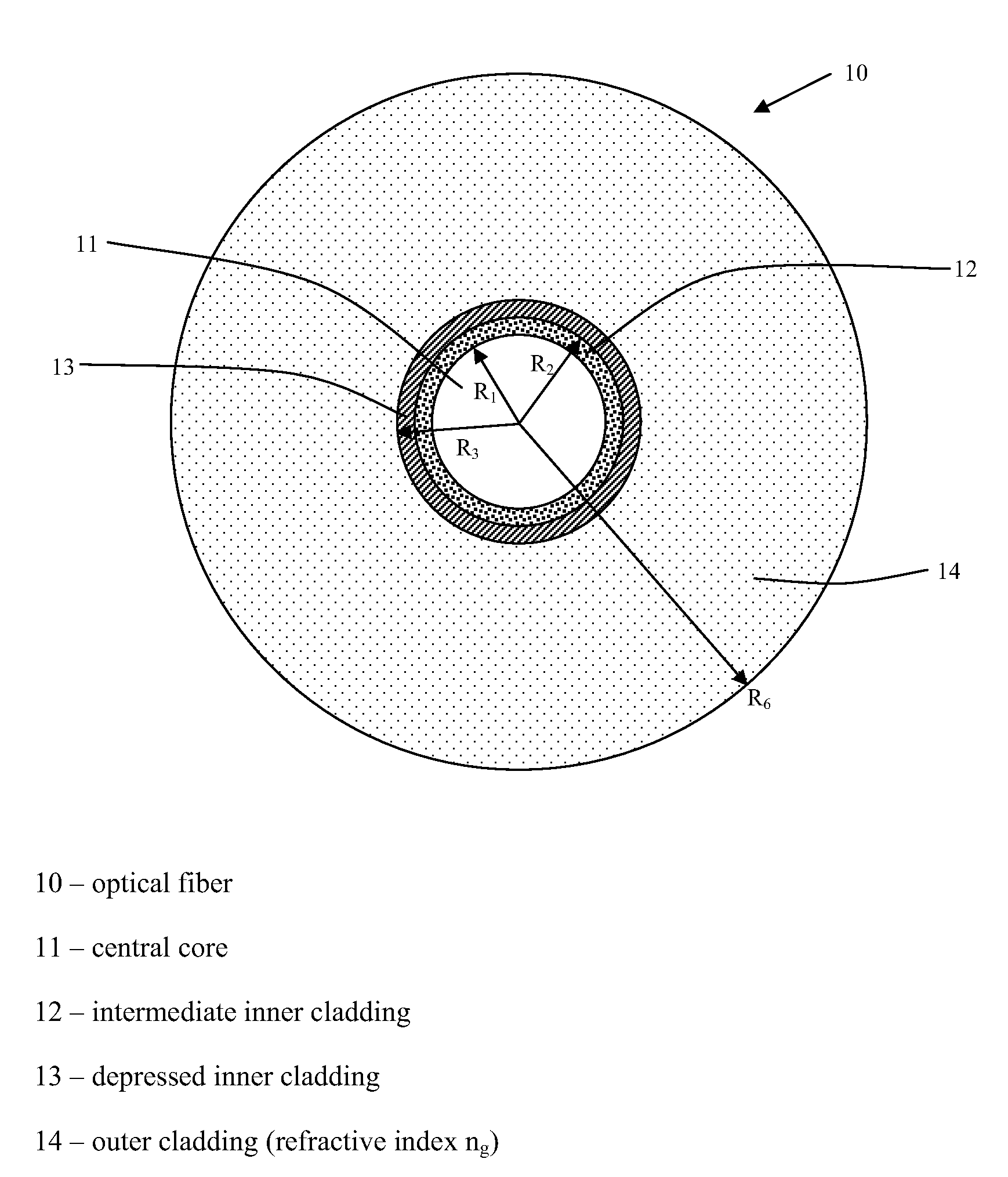
[0036]To compensate the negative chromatic dispersion or to offset an overcompensation, the invention proposes the use of a chromatic dispersion compensating optical fiber 10 having a particular refractive index profile with a central core 11, an intermediate cladding 12, and an inner depressed cladding 13, making it possible at a wavelength of 1550 nm to achieve a chromatic dispersion of 21 ps / (nm·km) or higher with a FOM value of 105 ps / nm / dB or higher. See FIG. 1.

[0037]With the presence of the depressed inner cladding, it is possible to achieve the desired chromatic dispersion value with low bending and microbending losses. The distancing of this depressed cladding from the central core makes it possible to limit transmission losses. The radius r3 of this depressed cladding is typically less than 16 microns to limit manufacturing costs related to depositing too large of a section of doped silica (e.g., doped with fluorine).

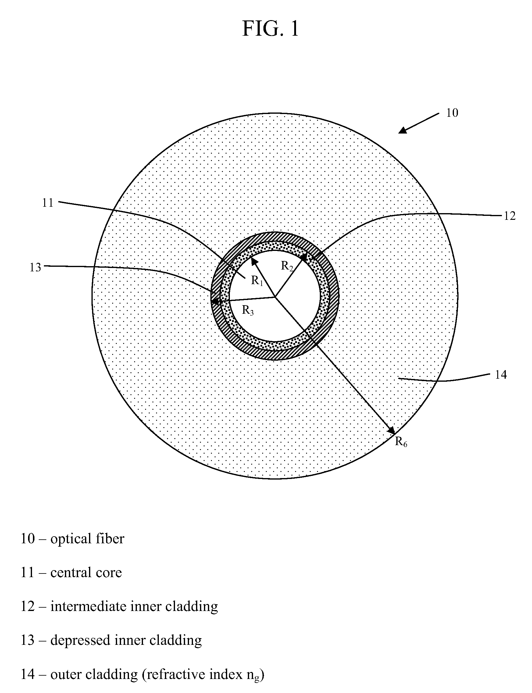
[0038]FIG. 2 schematically illustrates a possible refract...


PUM


Abstract

Disclosed is a chromatic dispersion compensating optical fiber comprising a central core, an intermediate cladding having a width (r2−r1) of 2.0 microns or greater, and a depressed inner cladding having a refractive index difference Dn3 with the external optical cladding of −3.0×10⁻³ or lower. At a wavelength of 1550 nm, the optical fiber exhibits a positive chromatic dispersion of 21 ps / (nm·km) or higher and a ratio of mode radius to intermediate cladding radius of (W02 / r2) of 0.7 or less. The present optical fiber has a good figure of merit value and limited bending and microbending losses. The optical fiber can be rolled up in a housing of reduced size in a chromatic dispersion compensating optical module having limited insertion losses and reduced polarization mode dispersion.

Description

CROSS-REFERENCE TO PRIORITY APPLICATIONS[0001]This application hereby claims the benefit of pending French Application No. 06 / 03928 (filed May 3, 2006 at the French Patent Office), which is hereby incorporated by reference in its entirety.FIELD OF THE INVENTION[0002]The present invention relates to optical fiber transmissions and, more specifically, to the compensation of the chromatic dispersion in fiber optical transmission systems.BACKGROUND OF THE INVENTION[0003]For optical fibers, the refractive index profile is generally qualified in relation to the graphical representation of the function that associates the refractive index with the fiber radius. Conventionally, the distance r to the center of the fiber is shown along the abscissa, and the difference between the refractive index and the refractive index of the external cladding of the optical fiber along the ordinate axis. The refractive index profile, therefore, is referred to as “step,”“trapezoidal,” or “triangular” profil...

Claims


Application Information

Patent Timeline
Patent Type & Authority Patents(United States)
IPC IPC(8): G02B6/02
CPCG02B6/02014G02B6/0365G02B6/02266G02B6/02019
Inventor DE MONTMORILLON, LOUIS-ANNEMOLIN, DENISBIGOT-ASTRUC, MARIANNESILLARD, PIERRE
Owner DRAKA COMTEQ BV
Why Eureka
Try Eureka