Object-based raster trapping

a raster trapping and object technology, applied in the field of computer graphics, can solve the problems of large computation costs, inconvenient use, and many designers who do not like the visual impact of trapping their designs

Active Publication Date: 2008-04-15
GLOBAL GRAPHICS SOFTWARE
View PDF9 Cites 9 Cited by
  • Summary
  • Abstract
  • Description
  • Claims
  • Application Information

AI Technical Summary

Problems solved by technology

Many designers do not like the visual impact of trapping their designs.
Trapping, when used, involves notoriously extensive computation.

Method used


Image

  • Object-based raster trapping
  • Object-based raster trapping
  • Object-based raster trapping

Examples


Embodiment Construction

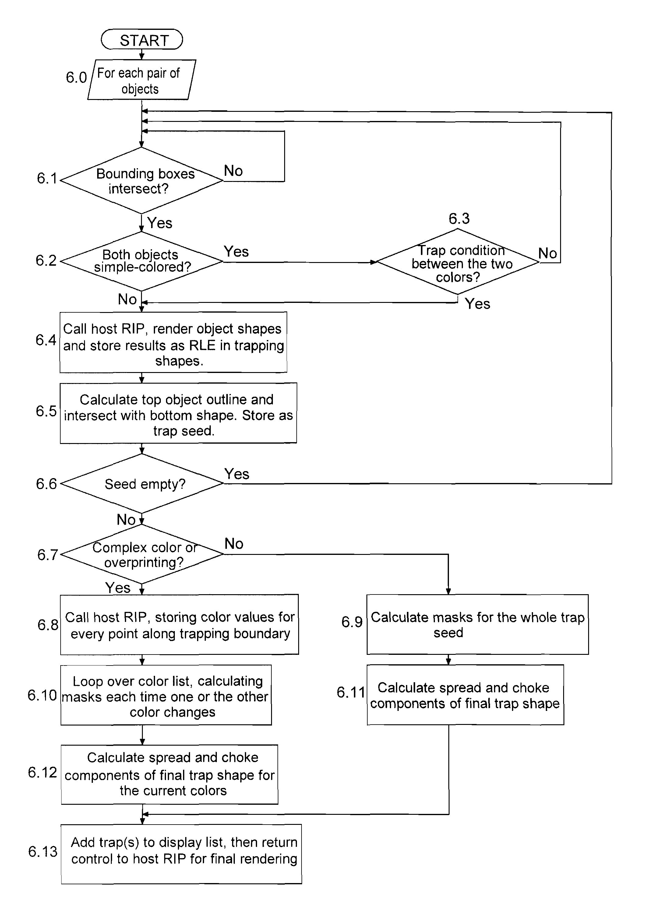
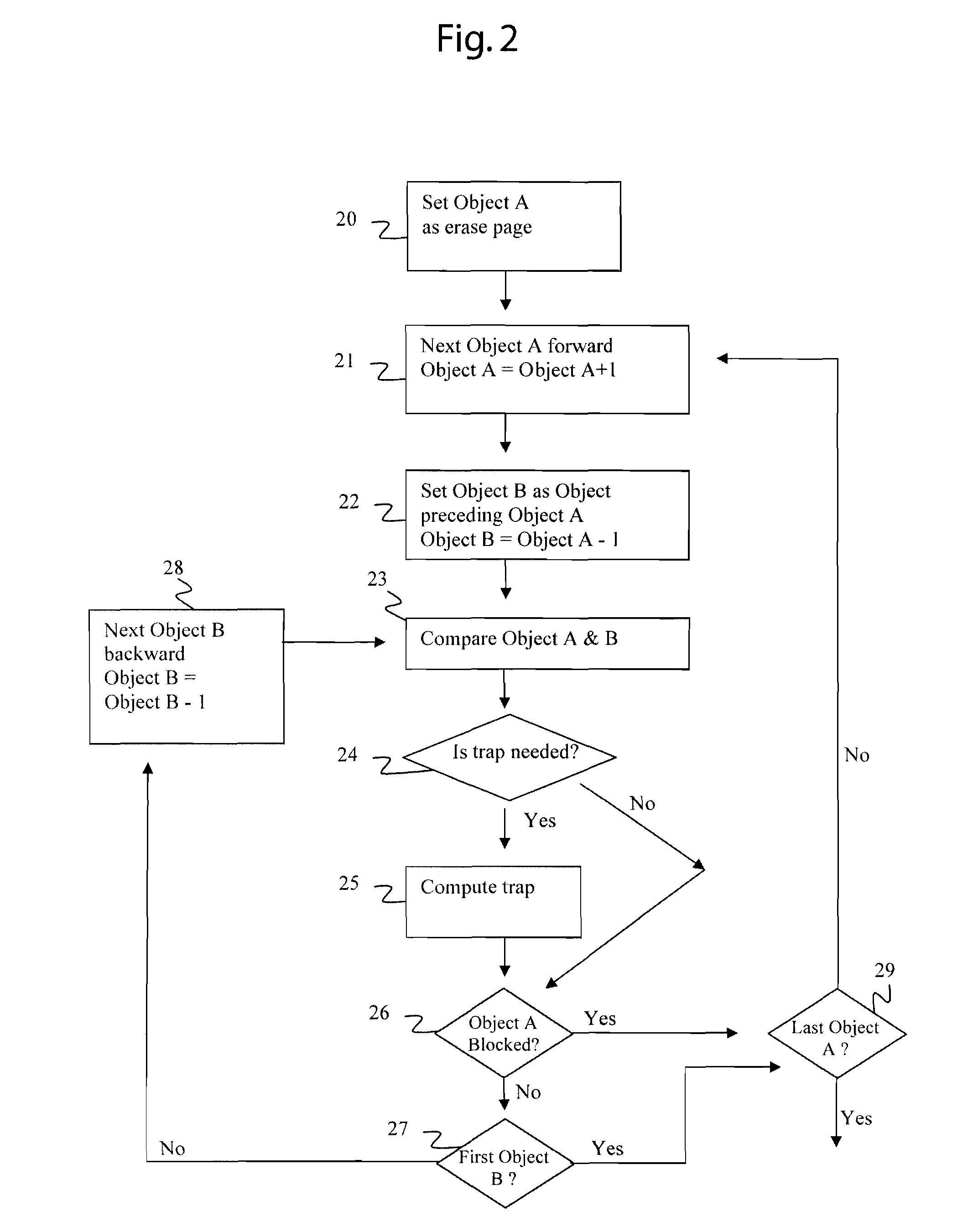
[0019]In the preferred embodiment of the invention, a trapping engine uses simple bounding boxes, colors, and temporal order information, to eliminate the possibility of trapping many pairs of objects without ever having to calculate their exact shapes. By considering the temporal order of the objects in a page, such a z-order display list, the trapping engine can quickly reject the possibility of trapping in areas where it is not necessary. Once a pair of objects that may need trapping has been identified, the rasterizer of the host Raster Image Processor (RIP) is used to calculate the pixels (and pixel values) for these objects. The rendition of pixels, which may be in various forms such as RLE shapes, is then processed by the engine to generate the ideal trap shape.

[0020]The trapping engine has the advantage of being easy to integrate into an existing RIP implementation, since it uses much of the functionality which a RIP must already necessarily provide in order to rasterize a p...


PUM


Abstract

Trapping graphics during pre-press workflow involves intensive computation. In this invention, the trapping engine uses simple bounding boxes, colors, and temporal order information, to eliminate the possibility of trapping many pairs of objects without ever having to calculate their exact shapes. By considering the temporal order of the objects in a page, such a z-order display list, the trapping engine can quickly reject the possibility of trapping in areas where it is not necessary.

Description

[0001]This application claims the benefit of U.S. Provisional Patent Application Ser. No. 60 / 476,410, filed Jun. 6, 2003, which is hereby incorporated by reference in its entirety.FIELD OF THE INVENTION[0002]This invention relates to the field of computer graphics and more particularly pre-press workflows using trapping.BACKGROUND OF THE INVENTION[0003]Current pre-press workflow and desktop publishing use an electronic page description file to track the specifications of how the page should be appear when printed or displayed. The file is a digital representation of the page to be printed. To print or display the page, it is translated into a scheme of pixels by a process called rasterization. The pixels correlate to locations on the page and represent black and white, shades of gray, or colors that make up the page. The output device, such as printer or monitor, can render the page according to the pixels. Some pre-printing processes use a display list which is an intermediary file...

Claims


Application Information

Patent Timeline
Patent Type & Authority Patents(United States)
IPC IPC(8): G06K9/00G06K15/02H04N1/58
CPCG06K15/02G06K15/1826H04N1/58
Inventor WILSON, JONATHAN ROBERT
Owner GLOBAL GRAPHICS SOFTWARE
Why Eureka
Try Eureka