Transmitter and/or receiver arrangement of optical signal transmission

a technology of optical signal and receiver, applied in the direction of optics, optical elements, instruments, etc., can solve the problems of high-frequency applications that are not suitable to a limited extent, and high-frequency packages with lateral lead-through are very complex and expensive, so as to achieve simple and low-cost production

Inactive Publication Date: 2008-04-15
II VI DELAWARE INC
View PDF19 Cites 8 Cited by
  • Summary
  • Abstract
  • Description
  • Claims
  • Application Information

AI Technical Summary

Benefits of technology

[0005]Starting out from this prior art, the present invention is directed to a transmitting and / or receiving arrangement for optical signal transmission which, while of a simple and low-cost construction, can be used even at high data rates above 1 Gbit / s.

Problems solved by technology

Transmitting and / or receiving arrangements for optical signal transmission with TO packages have the disadvantage that they are only suitable to a limited extent for high-frequency applications.
Such high-frequency packages with lateral lead-through are very complex and expensive.

Method used


Image

  • Transmitter and/or receiver arrangement of optical signal transmission
  • Transmitter and/or receiver arrangement of optical signal transmission
  • Transmitter and/or receiver arrangement of optical signal transmission

Examples


Embodiment Construction

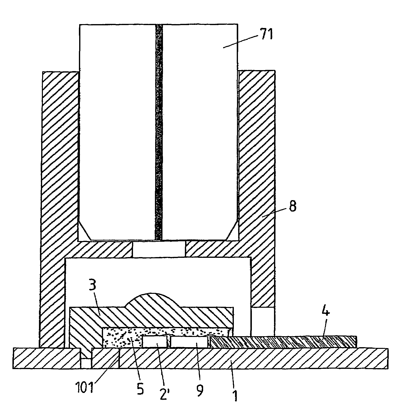
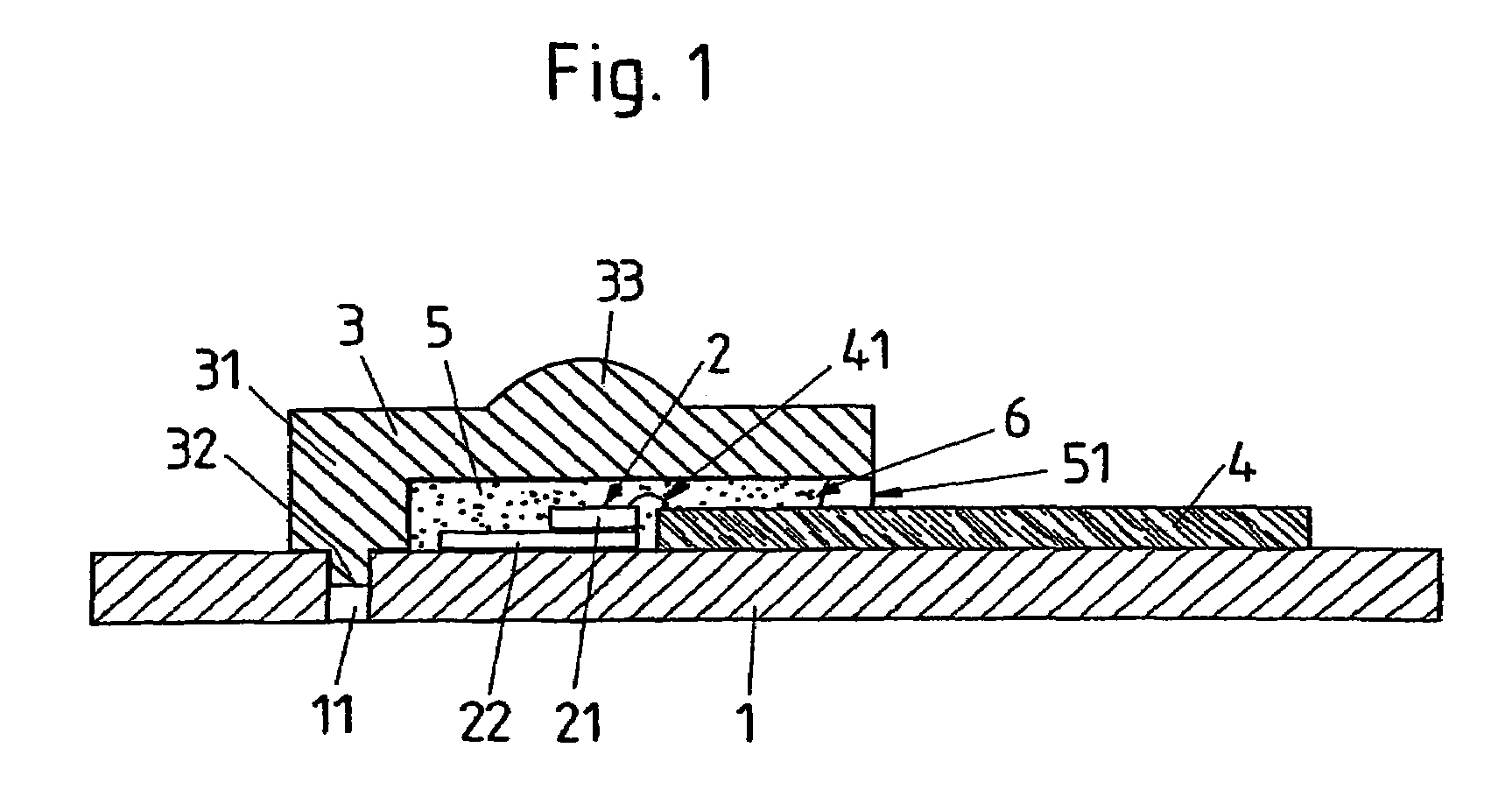
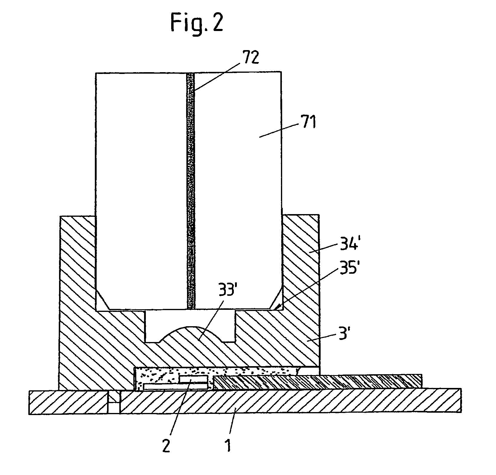
[0030]According to FIG. 1, the transmitting and / or receiving device comprises a base plate 1, an optical chip 2 as the transmitting and / or receiving element, a beam-shaping element 3 and a carrier element 4 for electrical line feeds.

[0031]It is preferred for the base plate 1 to be a leadframe or part of a leadframe, the surface of which serves as a mounting area for the further components. The optical chip 2 is arranged directly on the base plate 1 or the leadframe. In the exemplary embodiment represented, it comprises an optical transmitting element 21, for example a laser diode or a light-emitting diode, and an optical receiving element 22, for example a photodiode, which are arranged one above the other by a chip-on-chip mounting technique. Alternatively, only one transmitting element 21 or only one receiving element 22 is provided.

[0032]It is also pointed out that the transmitting element 21 does not have to be arranged above the receiving element 22. For instance, the transmitt...


PUM


Abstract

An optical transmitting and / or receiving arrangement including an optical element mounted in an intermediate space between a base plate and a lens. The lens is supported by a structure that is mounted on the base plate, and a carrier element mounted on the base plate and has an end portion extending through an opening formed in the structure and into the intermediate space. The end portion of the carrier element is positioned adjacent to the optical element, and includes electrical feed lines that are connected to the optical element by wires or bands. A transparent casting compound is then injected through the opening into the intermediate space.

Description

FIELD OF THE INVENTION[0001]The invention relates to a transmitting and / or receiving arrangement for optical signal transmission.BACKGROUND OF THE INVENTION[0002]In optical communications transmission, transmitting and / or receiving arrangements are used to couple light signals into a waveguide and / or to detect optical signals received by a waveguide. For data communication applications, compact and low-cost transmitting and / or receiving arrangements are required both for multi-mode optical waveguides and for single-mode optical waveguides.[0003]There are known, for example from EP 0 684 651 A2, transmitting and / or receiving arrangements in which a transmitting and / or receiving element is arranged in a hermetically sealed manner in what is known as a TO package. TO packages are standard packages known in the prior art for optical transmitting or receiving elements, the form of which resembles the case of a (classic) transistor, which however have on the upper side a glass window for ...

Claims


Application Information

Patent Timeline
Patent Type & Authority Patents(United States)
IPC IPC(8): H04B10/00H04B10/12G02B6/42
CPCG02B6/4204G02B6/423G02B6/4201H01L2224/48091H01L2924/00014G02B6/4279
Inventor KROPP, JORG-REINHARDT
Owner II VI DELAWARE INC
Why Eureka
Try Eureka