Tie strap assembly

a technology of tie straps and straps, which is applied in the direction of machine supports, transportation and packaging, and other domestic objects, and can solve problems such as difficulty in adjusting the fastener for users

Inactive Publication Date: 2008-04-22
ILLINOIS TOOL WORKS INC
View PDF11 Cites 22 Cited by
  • Summary
  • Abstract
  • Description
  • Claims
  • Application Information

AI Technical Summary

Benefits of technology

[0012]The strap may connect to the lock housing through a lock housing beam, wherein a distal end of the strap is configured to pass into the lock passage of the lock housing to form a bundling loop. The lock housing prevents the strap from retreating within the lock passage, or otherwise moving in a direction opposite to that of the direction in which it entered the lock passage.

Problems solved by technology

A user may find it difficult to adjust the fastener 22 with respect to the cinched wire bundle, due to the added pressure exerted by the wire bundle into the fastener 22.

Method used


Image

  • Tie strap assembly
  • Tie strap assembly
  • Tie strap assembly

Examples


Embodiment Construction

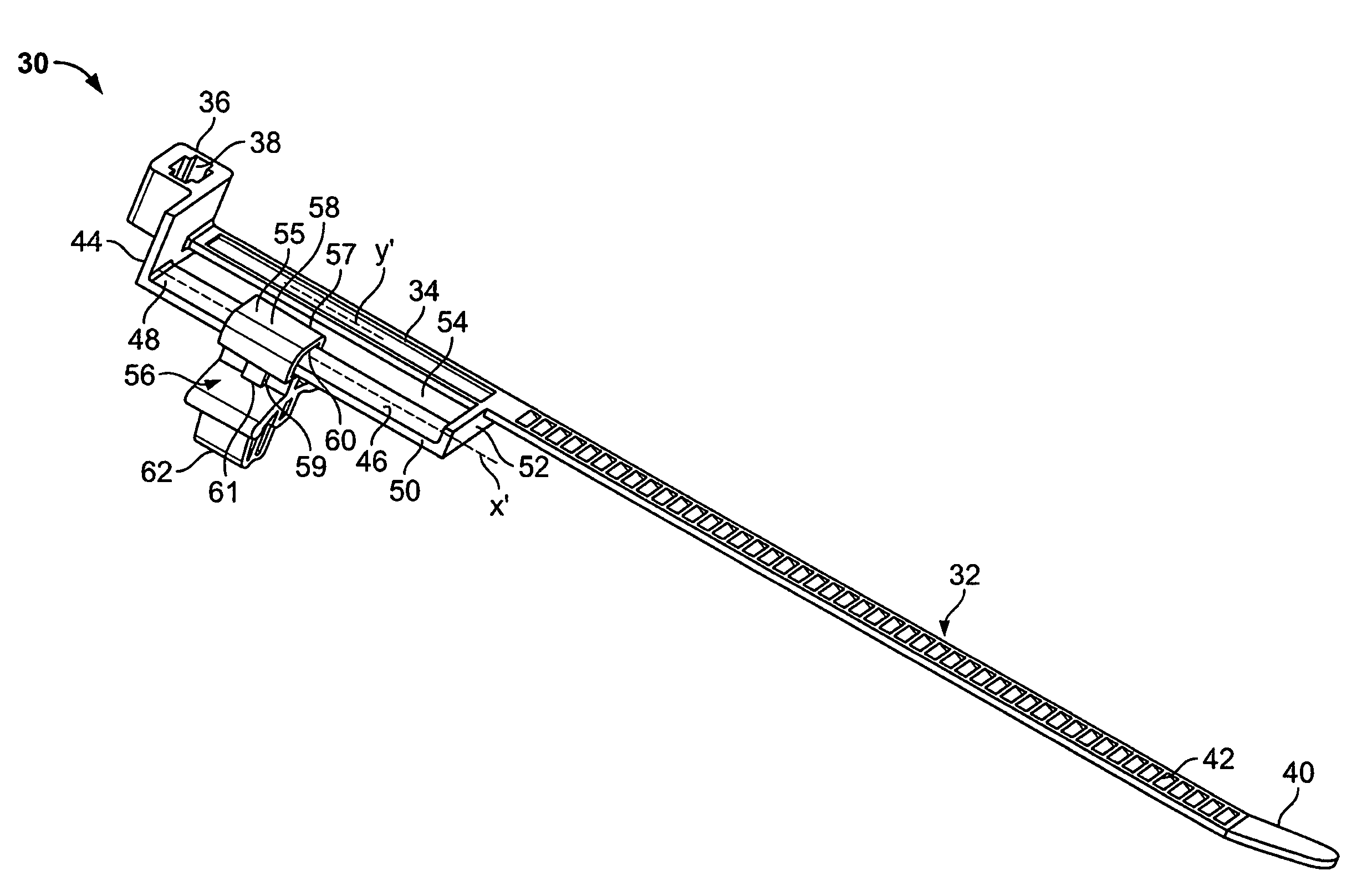
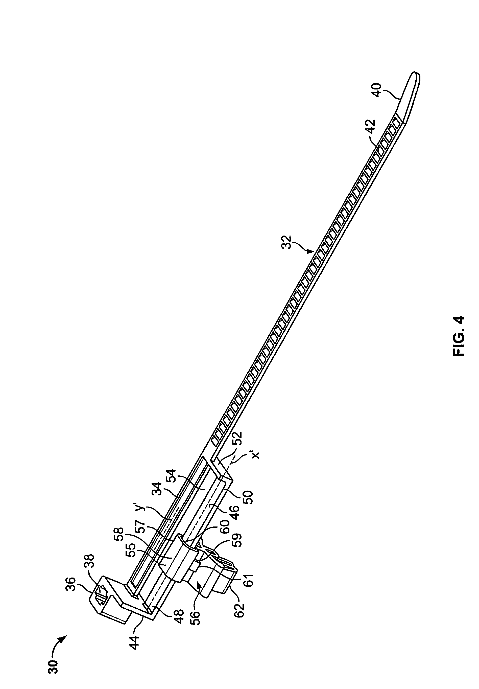
[0025]FIG. 4 illustrates an isometric view of a tie strap assembly 30 according to an embodiment of the present invention. The tie strap assembly 30 includes a strap 32 integrally connected to a lock housing beam 34, which is in turn integrally connected to a lock housing 36. The lock housing 36 includes a lock passage 38 formed therethrough. A distal end 40 of the strap 32 is fed into the lock passage 38, thereby forming a loop around items to be bundled. The distal end 40 is passed through the lock passage 38 so that features on the strap 32, such as hooks, claps, barbs, or other such protrusions 42 engage reciprocal features (not shown) within the lock housing 36 that prevent the strap 32 from retreating within the lock passage 38.

[0026]The lock housing 36 includes an extension wall or beam 44 that is integrally connected to a fastener beam or rail 46 that may be parallel to, but offset from, the beam 34. One end 48 of the fastener beam 46 integrally connects to the extension wal...


PUM


Abstract

A tie strap assembly includes a strap, a fastener rail or beam and a fastener. The strap is connected to a lock housing, wherein a distal end of the strap is configured to pass into a lock passage of the lock housing to form a loop. The fastener rail is offset from the strap, such that the strap does not directly contact the fastener rail. A fastener is slidably secured on the fastener rail, and is therefore, not in contact with the strap. Wires bundled within the strap do not contact the fastener. Thus, the fastener may be easily slidably adjusted on the fastener rail without interference from bundled wires or the strap.

Description

RELATED APPLICATIONS[0001]This application relates to and claims priority benefits from U.S. Provisional Patent Application 60 / 717,091 entitled “Tie Strap,” filed Sep. 14, 2005, which is hereby incorporated by reference in its entirety.FIELD OF THE INVENTION[0002]Embodiments of the present invention generally relate to a tie strap assembly, and more particularly to a tie strap assembly configured to wrap around and secure various items, such as wire bundles.BACKGROUND OF THE INVENTION[0003]Tie straps are used in many applications across many industries in order to fasten objects of varying dimensions. Objects, such as wires, may be bundled together with a single tie strap.[0004]FIG. 1 illustrates an isometric exploded view of a conventional tie strap assembly 10. The tie strap assembly 10 includes a flexible strap 12 having a lock housing 14. The lock housing 14 includes walls 16 that define a lock passage 18. A distal end 20 of the strap 12 is positioned through the lock passage 18...

Claims


Application Information

Patent Timeline
Patent Type & Authority Patents(United States)
IPC IPC(8): B65D63/00
CPCF16L3/137F16L3/233H02G3/30Y10T292/48
Inventor KWILOSZ, MARK J.
Owner ILLINOIS TOOL WORKS INC
Why Eureka
Try Eureka