
Image forming apparatus and method

a technology of image forming and forming apparatus, which is applied in the direction of measuring apparatus components, instruments, printing, etc., can solve the problems of inability to meet high-speed printing, inability to print the other side, and inability to achieve high-speed printing, etc., to achieve stable transferability, stable image quality, and high image quality

Inactive Publication Date: 2008-04-22
FUJIFILM CORP
View PDF17 Cites 51 Cited by
  • Summary
  • Abstract
  • Description
  • Claims
  • Application Information

AI Technical Summary

Benefits of technology

[0014]The present invention has been contrived in view of such circumstances, and an object thereof is to provide an image-forming apparatus and image-forming method that realize high-speed, high-quality double-sided image recording.

Problems solved by technology

However, the method in which printing is carried out on one side, the paper is reversed, and the other side is then printed is not suitable for high-speed printing because the time normally required to print two pages is needed to print a single page.
Furthermore, the image quality is liable to be degraded by ink transfer, soiling, and other drawbacks when printing is carried out on the other side without the ink being adequately fixed on the previously printed side.
In the inkjet printer described in Japanese Patent Application Publication No. 2000-272111, it is difficult to assure positional accuracy between the two head groups and the recording medium depending on the quality and thickness of the printing medium.
Also, it is impossible to ignore force applied in the gravitational direction because at least one of the head groups does not discharge downward, and it becomes difficult to match the image conditions between the front and reverse sides.
In the inkjet double-sided print method and apparatus described in Japanese Patent Application Publication No. 2003-80688, there is a possibility that ink will not be stably transferred and fixed on the paper, and the quality of the resulting image is liable to considerably vary depending on the type and thickness of the paper.

Method used


Image

  • Image forming apparatus and method
  • Image forming apparatus and method
  • Image forming apparatus and method

Examples


Embodiment Construction

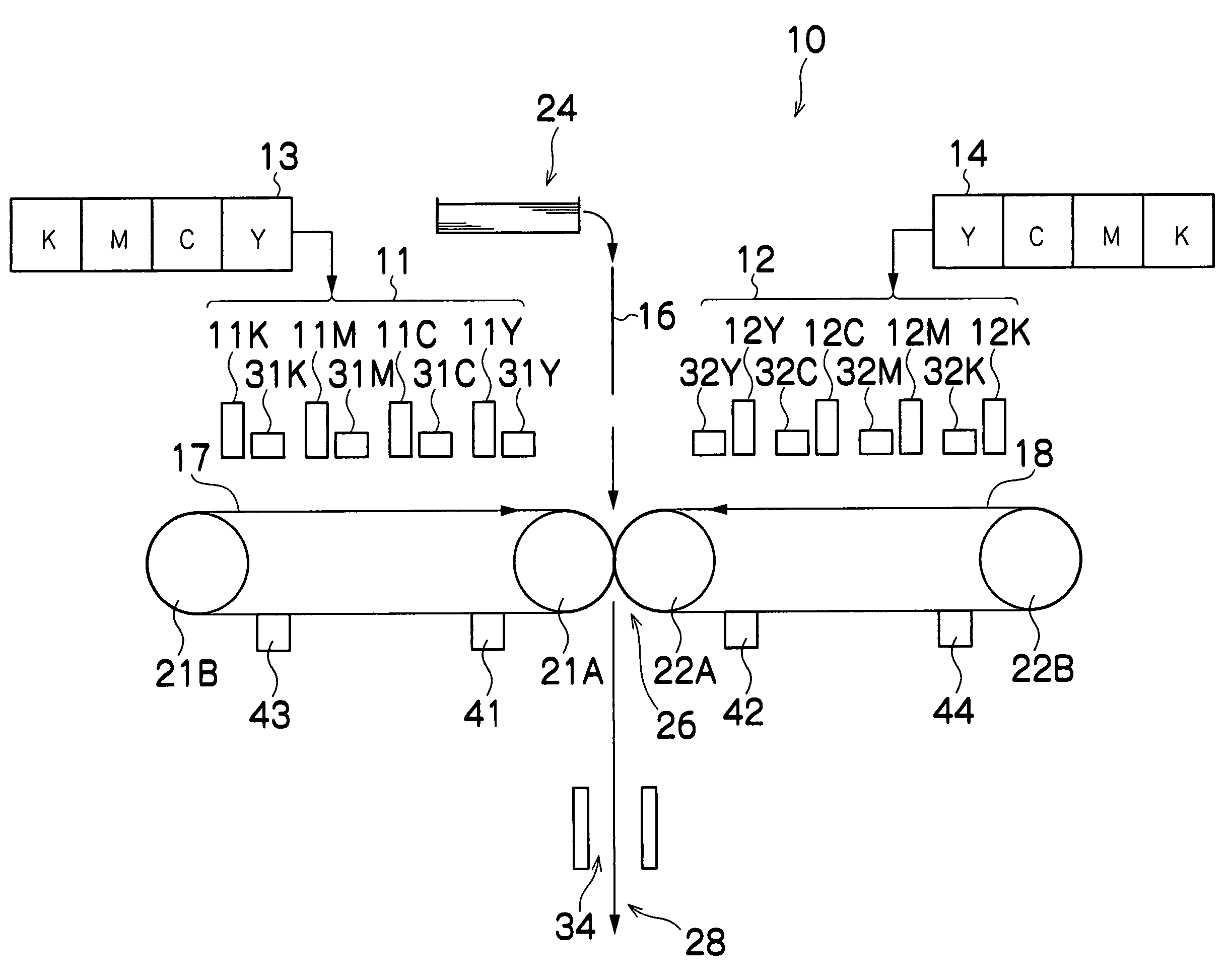
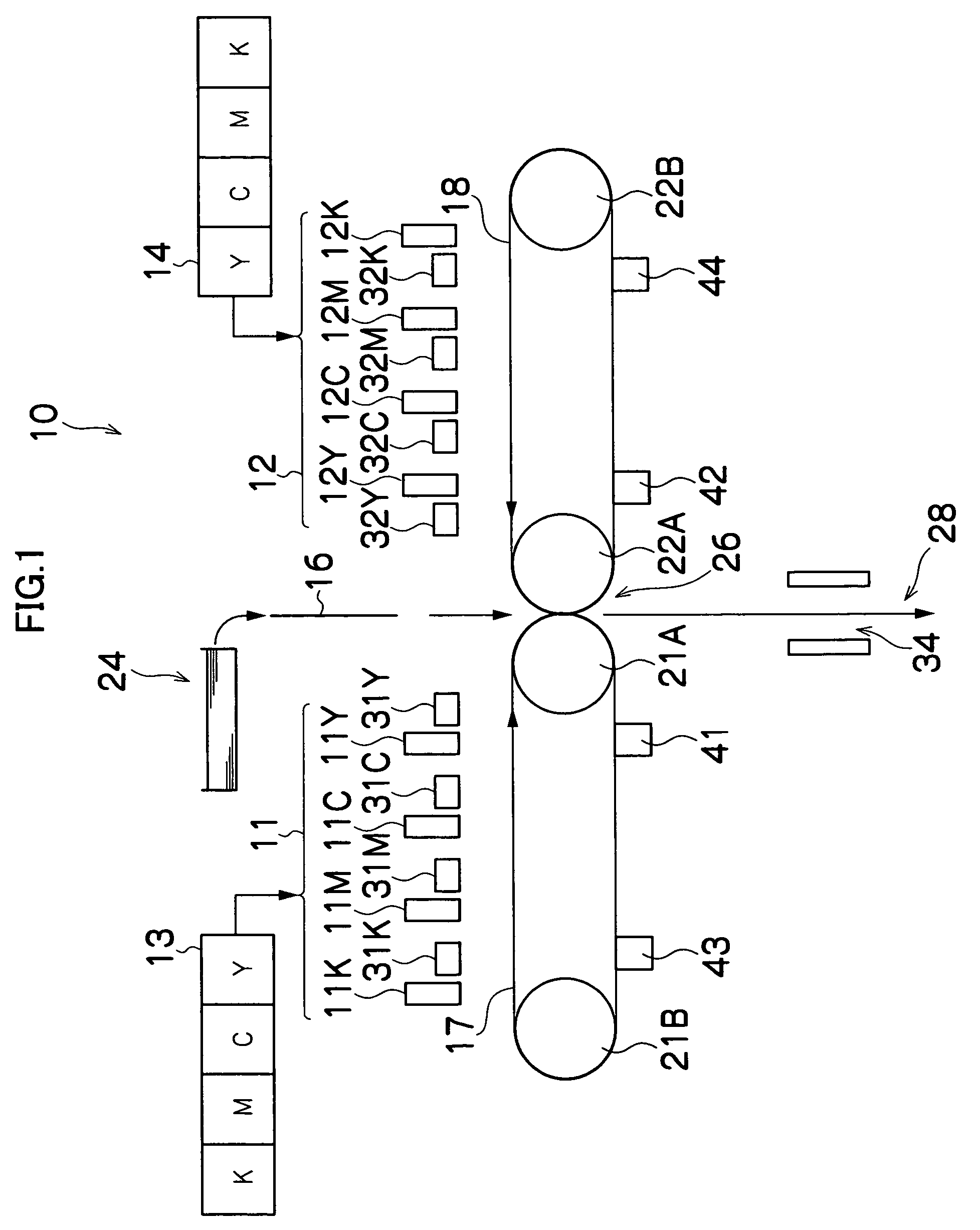
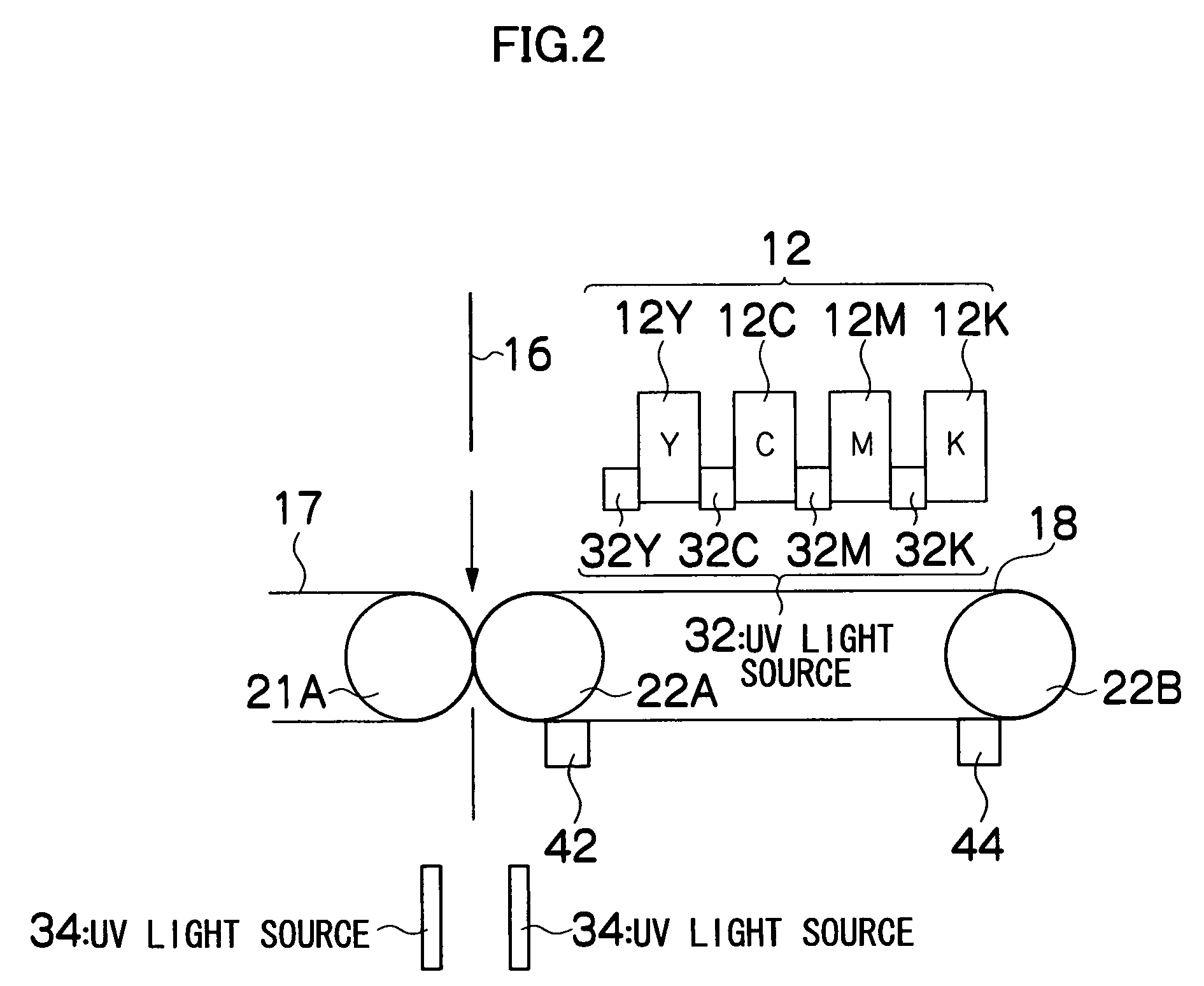
[0053]FIG. 1 is a general schematic drawing of an inkjet recording apparatus according to an embodiment of the present invention. As shown in FIG. 1, the inkjet recording apparatus 10 is provided with a first head group 11 having a plurality of print heads 11K, 11C, 11M, and 11Y provided for each color of ink; a second head group 12 having print heads 12K, 12C, 12M, and 12Y; an ink storing and loading unit 13 for storing ink to be fed to the print heads 11K, 11C, 11M, and 11Y incorporated in the first head group 11; an ink storing and loading unit 14 for storing ink to be fed to the print heads 12K, 12C, 12M, and 12Y incorporated in the second head group 12; a first transfer belt 17 on which an image is formed by ink ejected from the first head group 11 and which is used for transferring the image to the first surface of a recording medium 16; and a second transfer belt 18 on which an image is formed by ink ejected from the second head group 12 and which is used for transferring the...


PUM


Abstract

The image forming apparatus comprises: a first inkjet head which ejects ink for forming a first image to be recorded on a recording medium; a first intermediate transfer medium on which the first image is formed by the ink ejected from the first inkjet head, the first intermediate transfer medium having a structure that includes an elastic body in a first image formation area in which the first image is formed; a second inkjet head which ejects ink for forming a second image to be recorded on the recording medium; a second intermediate transfer medium on which the second image is formed by the ink ejected from the second inkjet head, the second intermediate transfer medium having a structure that includes an elastic body in a second image formation area in which the second image is formed; and a transfer recording device which transfers and records the first image and the second image to a first surface of the recording medium in contact with the first image formation area and a second surface of the recording medium in contact with the second image formation area, while holding the recording medium between the first intermediate transfer medium and the second intermediate transfer medium, and conveying the recording medium with respect to the first intermediate transfer medium and the second intermediate transfer medium.

Description

BACKGROUND OF THE INVENTION[0001]1. Field of the Invention[0002]The present invention relates to an image forming apparatus and an image forming method, and more particularly to a double-sided image forming technique for forming a desired image on both sides of a recording medium.[0003]2. Description of the Related Art[0004]In recent years, inkjet printers are becoming more widely used as data output apparatuses for images, documents, and other forms of data. Inkjet printers drive nozzles or other recording elements provided to a print head in accordance with data, and data can be formed on recording paper or another recording medium by ink ejected from the nozzles.[0005]An inkjet printer moves a recording medium and a print head having a large number of nozzles in relation to each other, and an image is formed on the recording paper by ejecting ink droplets from the nozzles.[0006]Conventionally, inkjet printers have been used as an output medium for small-sized, small-scale printin...

Claims


Application Information

Patent Timeline
Patent Type & Authority Patents(United States)
IPC IPC(8): B41J2/01B41J2/145
CPCB41J2/01B41J2002/012B41J2202/20
Inventor KONNO, MASAAKI
Owner FUJIFILM CORP
Learn More