Rider restriction device of two-wheeled vehicle
a two-wheeled vehicle and restriction device technology, applied in the direction of vehicular safety arrangements, pedestrian/occupant safety arrangements, cycle equipment, etc., can solve the problem that the technology is not applicable to the vehicle, and achieve the effect of restricting the plastic deformation of the pad support member, and reducing the risk of accidents
- Summary
- Abstract
- Description
- Claims
- Application Information
AI Technical Summary
Benefits of technology
Problems solved by technology
Method used
Image
Examples
first embodiment
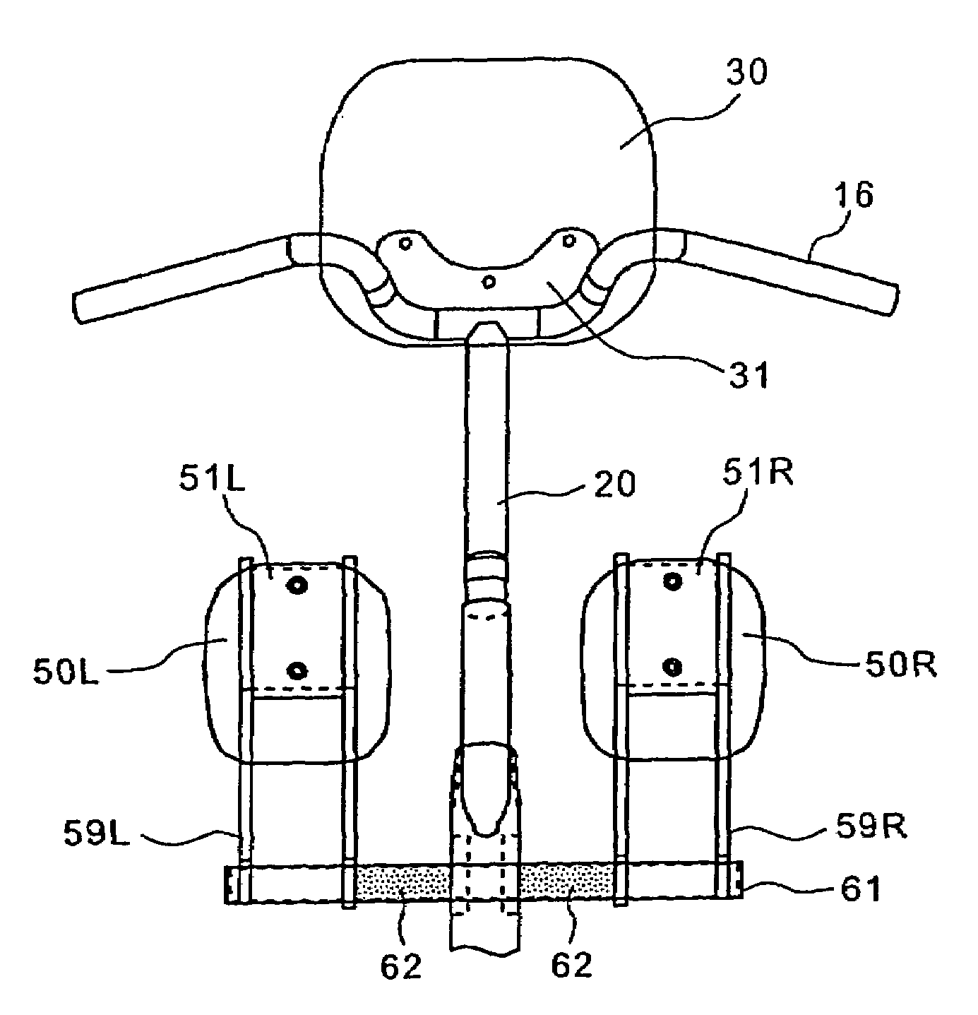
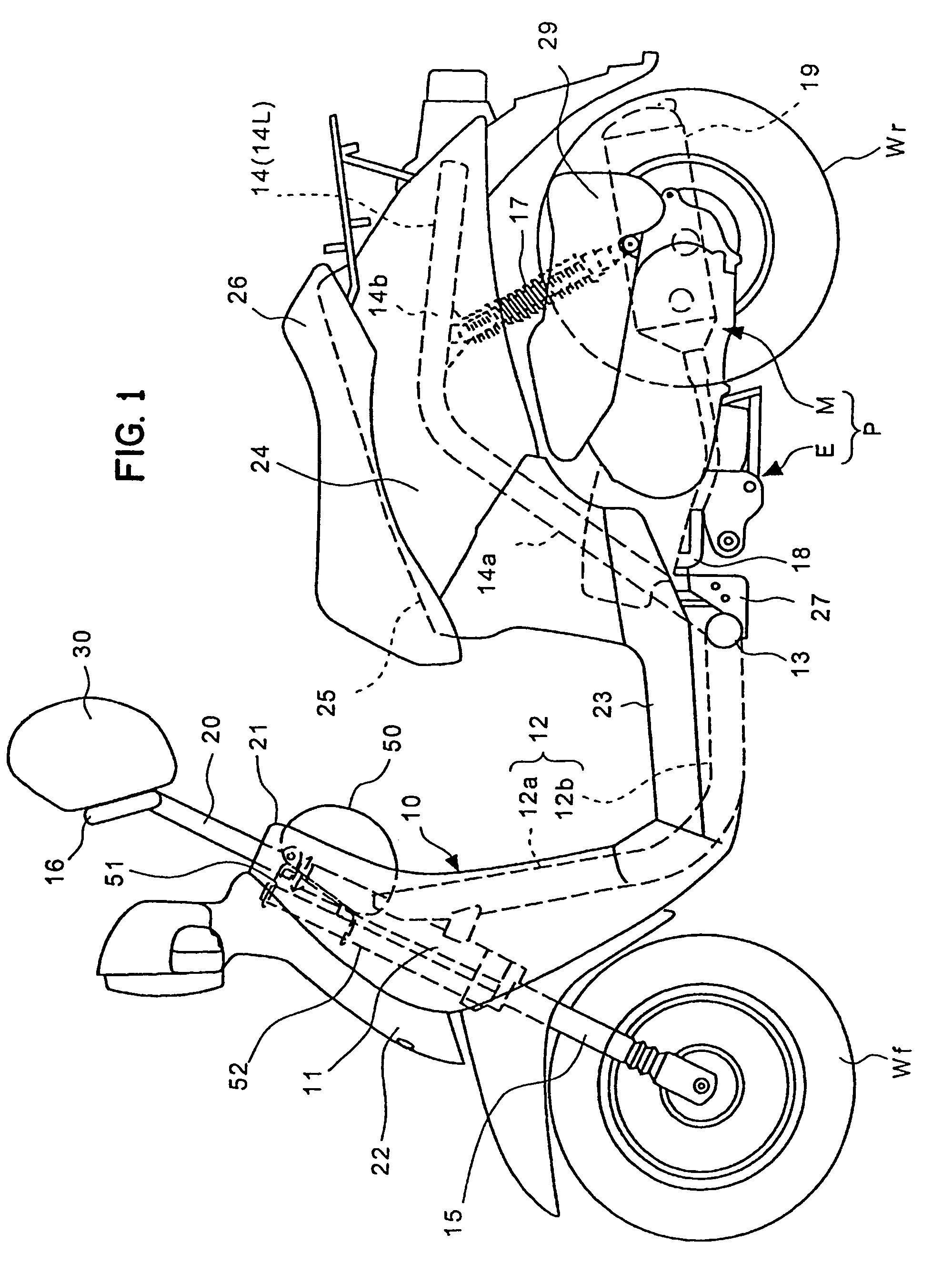
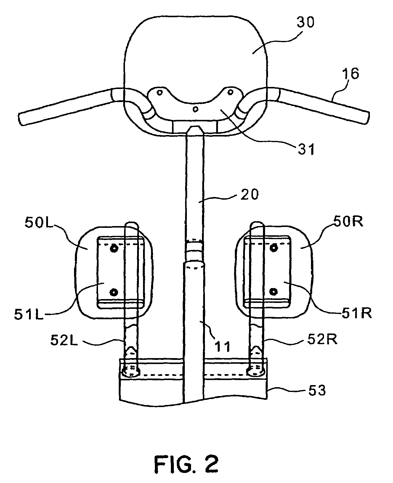
[0033]FIG. 5 is a cross-sectional view of the above-mentioned load absorbing portion and symbols equal to the above-mentioned symbols indicate identical or similar portions. In this embodiment, the pad support pipe 52 has a lower end portion thereof fixed to a connecting member 53 in a state that the lower end portion is inserted in and penetrates the connecting member 53, while a longitudinal elastic member 55 penetrates in and is fixed to the inside of the lower end portion.
[0034]In such a constitution, when a frontward load which exceeds a given reference value is applied to the above-mentioned knee portion pad 50, the above-mentioned pad support pipe 52 starts a deflection thereof. When a stress exceeds a yielding point of the pad support pipe 52, the plastic deformation starts and, as indicated by a chain line in the drawing, the pad support pipe 52 starts bending in the frontward direction.
[0035]FIG. 11 shows the relationship between a frontward moving amount of the above-ment...
second embodiment
[0037]FIG. 6 is a cross-sectional view of the above-mentioned load absorbing portion and symbols equal to the above-mentioned symbols indicate identical or similar portions. In this embodiment, the pad support pipe 52 has a lower end portion thereof fixed to a connecting member 53 in a state that the lower end portion is inserted in and penetrates the connecting member 53, while a coil spring 56 penetrates in and is fixed to the inside of the lower end portion.
[0038]In such a constitution, when a frontward load which exceeds a given reference value is applied to the above-mentioned knee portion pad 50, the above-mentioned pad support pipe 52 starts a deflection thereof. When a stress exceeds a yielding point of is the pad support pipe 52, the plastic deformation starts and, as indicated by a chain line in the drawing, the pad support pipe 52 starts bending in the frontward direction. However, in this embodiment, since the coil spring 56 is inserted into the inside of a bent portion ...
third embodiment
[0039]FIG. 7 is a cross-sectional view of the above-mentioned load absorbing portion and symbols equal to the above-mentioned symbols indicate identical or similar portions. In this embodiment, the pad support pipe 52 has a lower end portion thereof fixed to a connecting member 53 in a state that the lower end portion is inserted in and penetrates the connecting member 53, while a bellows-like collapsible body 57 is formed in the vicinity of an upper portion of the connecting member 53.
[0040]In such a constitution, when a frontward load which exceeds a given reference value is applied to the above-mentioned knee portion pad 50, the above-mentioned pad support pipe 52 starts a deflection thereof. When a stress exceeds a stress limit of the bellows-like collapsible body 57, a front portion side of the bellows-like collapsible body 57 is collapsed and the plastic deformation in which a lower portion side of the bellows-like collapsible body 57 extends starts and hence, the pad support ...
PUM
 Abstract
Description
Claims
Application Information
 - R&D
- Intellectual Property
- Life Sciences
- Materials
- Tech Scout
- Unparalleled Data Quality
- Higher Quality Content
- 60% Fewer Hallucinations
Browse by: Latest US Patents, China's latest patents, Technical Efficacy Thesaurus, Application Domain, Technology Topic, Popular Technical Reports.
© 2025 PatSnap. All rights reserved.Legal|Privacy policy|Modern Slavery Act Transparency Statement|Sitemap|About US| Contact US: help@patsnap.com


