
Net-reinforced film structure with modified strand profile

a technology of netting strands and reinforced films, which is applied in the field of net-reinforced films, can solve the problems of weak seal, difficult to line up netting strands, and complicate the sealing process of netting, and achieves greater mechanical tolerances and strong seals

Inactive Publication Date: 2008-05-13
REYNOLDS CONSUMER PROD INC
View PDF28 Cites 0 Cited by
  • Summary
  • Abstract
  • Description
  • Claims
  • Application Information

AI Technical Summary

Benefits of technology

[0005]Accordingly, an object of the present invention is to provide a net-reinforced film that allows for stronger seals between pieces of film and, at the same time, allows for greater mechanical tolerances in the sealing process.
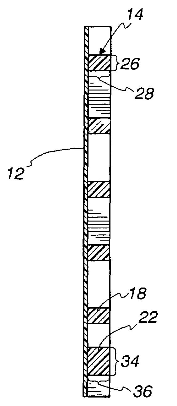
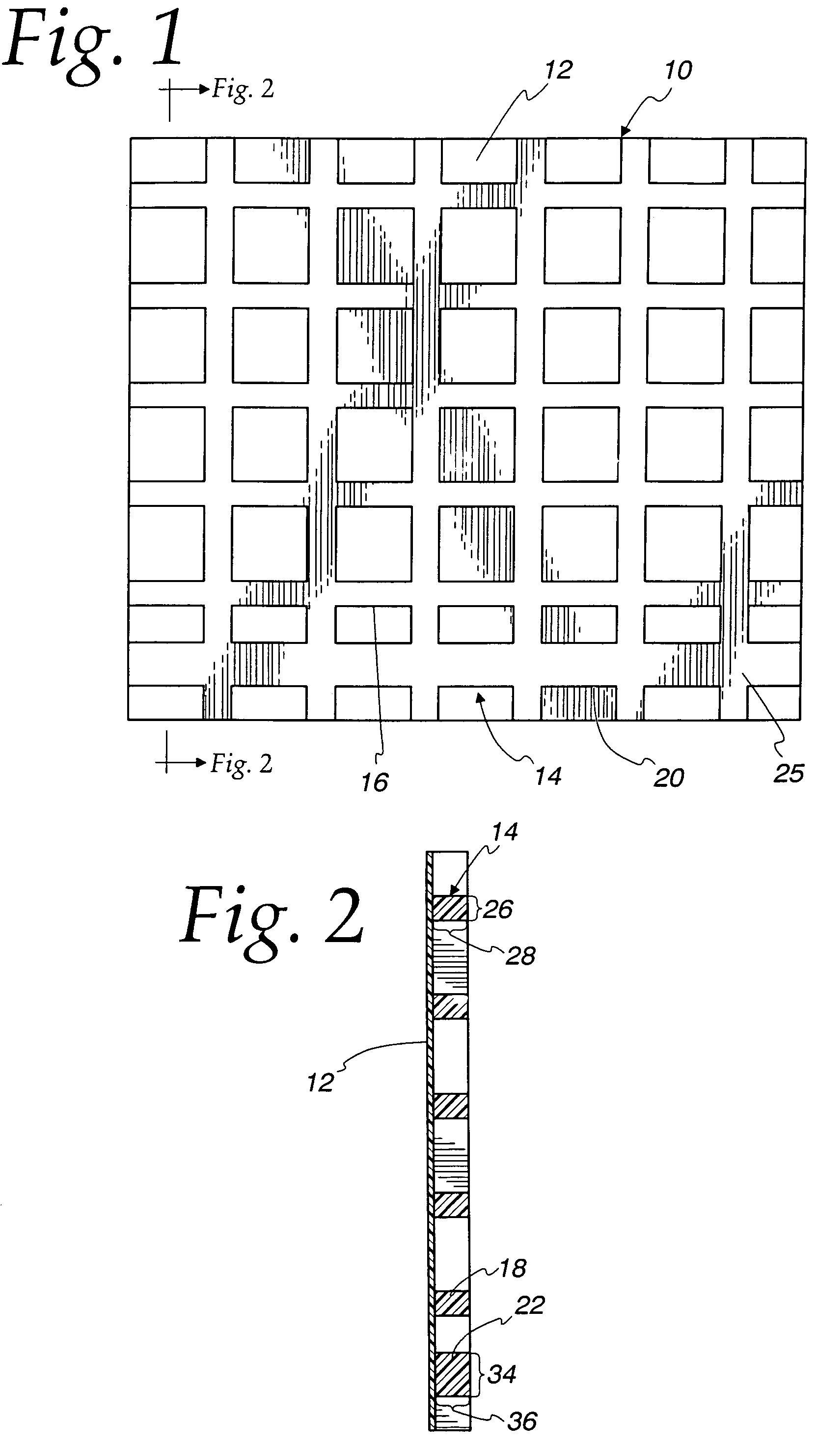
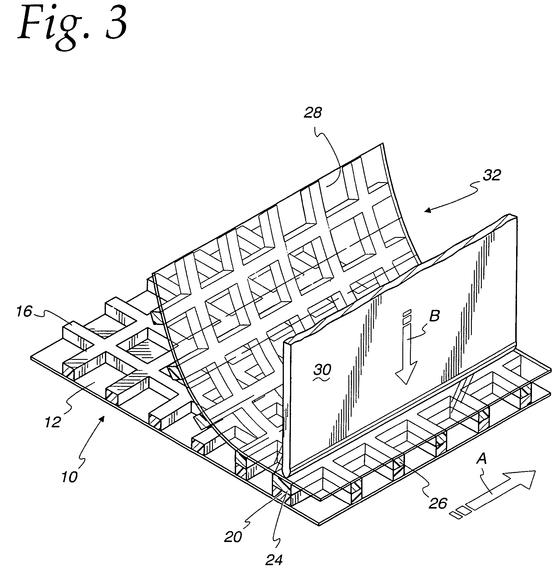
[0007]This and other objects are realized by providing a unique net-reinforced film structure. The net-reinforced film structure includes a film layer and a netting attached to the film layer having a pattern of netting strands. The netting strands are sealed to an opposing film structure along a generally linear seal area. The opposing film structure may be either a similar net-reinforced film or a standard non-reinforced film sheet. The netting strands in the non-sealed areas of the net-reinforced film structure are free from attachment to the opposing film structure. The netting strands along the linear seal area have a wider cross-section than the netting strands at the non-sealed areas, and this wider cross-section facilitates the sealing process.

Problems solved by technology

The addition of netting complicates the sealing process because it can be difficult to line up netting strands with each other or with a heating element to assure a complete and strong seal when net-reinforced films must be sealed to each other.
Further, sealing films along a thin netting strand can result in a weak seal.
This thinness at the seal points makes it difficult to achieve complete, strong seals because the manufacturer must perfectly align a thin seal strand, a heating element, and an opposing thin seal strand or film.

Method used


Image

  • Net-reinforced film structure with modified strand profile
  • Net-reinforced film structure with modified strand profile
  • Net-reinforced film structure with modified strand profile

Examples


Embodiment Construction

[0014]Turning now to the drawings, FIG. 1 of the drawings shows a top view of a net-reinforced film 10 embodying the present invention. The net-reinforced film 10 comprises a film layer 12 reinforced with a netting 14. In one embodiment, the film layer 12 is formed by coextrusion with the netting 14. In this embodiment, the film layer 12 may consist of a thermoplastic such as, for example, low-density polyethylene (LDPE), linear low-density polyethylene (LLDPE), high-density polyethylene (HDPE), metallocene, ethylene vinyl acetate (EVA), or blends of these. The netting 14 may consist of, for example, LLDPE, HDPE, polypropylene, polyethylene, polypropylene / polyethylene copolymer, or metallocene. The thermoplastics used to make the netting 14 and the film layer 12 are selected such that the netting can be bound to the film through coextrusion at the film formation step without the use of an additional adhesive layer.

[0015]The netting 14 is formed during the extrusion process such that...


PUM

PropertyMeasurementUnit
Lengthaaaaaaaaaa
Widthaaaaaaaaaa
Widthaaaaaaaaaa

Abstract

A net-reinforced film structure includes a film layer and a netting attached to the film layer having a pattern of netting strands. The netting strands are sealed to an opposing film structure, which may be either a similar net-reinforced film or a standard sheet of film, along a linear seal area. The netting strands in the non-sealed areas of the net-reinforced film structure are free from attachment to the opposing film structure. The netting strands along the linear seal area have a wider cross-section than the netting strands at the non-sealed areas, and this wider cross-section facilitates the sealing process.

Description

[0001]This is a division of application Ser. No. 09 / 510,857, filed Feb. 23, 2000 now U.S. Pat. No. 6,774,062.FIELD OF THE INVENTION[0002]The present invention relates generally to net-reinforced films and, more particularly, relates to a net-reinforced film having a modified netting strand profile to facilitate seal alignment and increase seal strength when the netting is sealed to an opposing netting strand or film.BACKGROUND OF THE INVENTION[0003]Film sheeting for use in waste bags, food storage bags, and other packages can be made stronger by the attachment or coextrusion of a netting onto the film layer. To use such films for bags or other packages, it is often necessary to seal one section of film to another in a heat seal process. Such seals are necessary, for example, at the sides and / or the bottoms of food storage bags and waste bags. The addition of netting complicates the sealing process because it can be difficult to line up netting strands with each other or with a heati...

Claims


Application Information

Patent Timeline
IPC IPC(8): B32B5/02B32B27/04B32B5/12B32B27/12
CPCB32B27/12Y10T428/24479Y10T428/2457Y10T428/24099Y10T428/24074Y10T428/24091Y10T442/10Y10T442/164Y10T442/169Y10T442/172Y10T442/183Y10T442/198
Inventor BRYNIARSKI, DAVID A.
Owner REYNOLDS CONSUMER PROD INC
Learn More